

A cover is fully closed, yet the device still reports it as open. A latch seems secure, but its status signal keeps changing. These problems do not necessarily mean the detector switch is defective. The pressing position, mounting bracket, or control circuit may also be responsible.
In security equipment, a detector switch helps confirm whether a cover, latch, or other moving component has reached the required position. Reliable operation depends on how the switch works with the surrounding mechanism and circuit—not just its datasheet specifications.
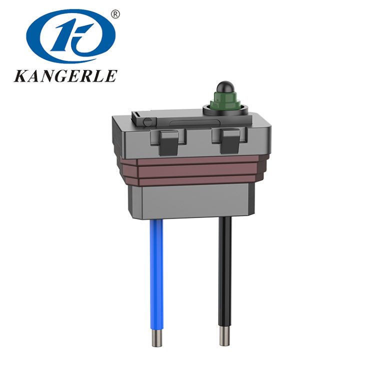
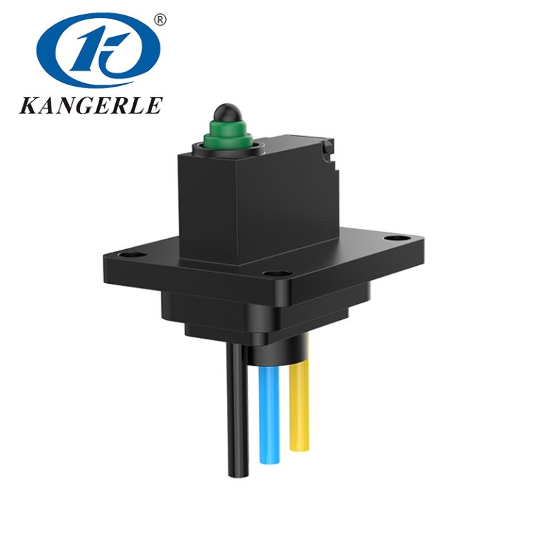
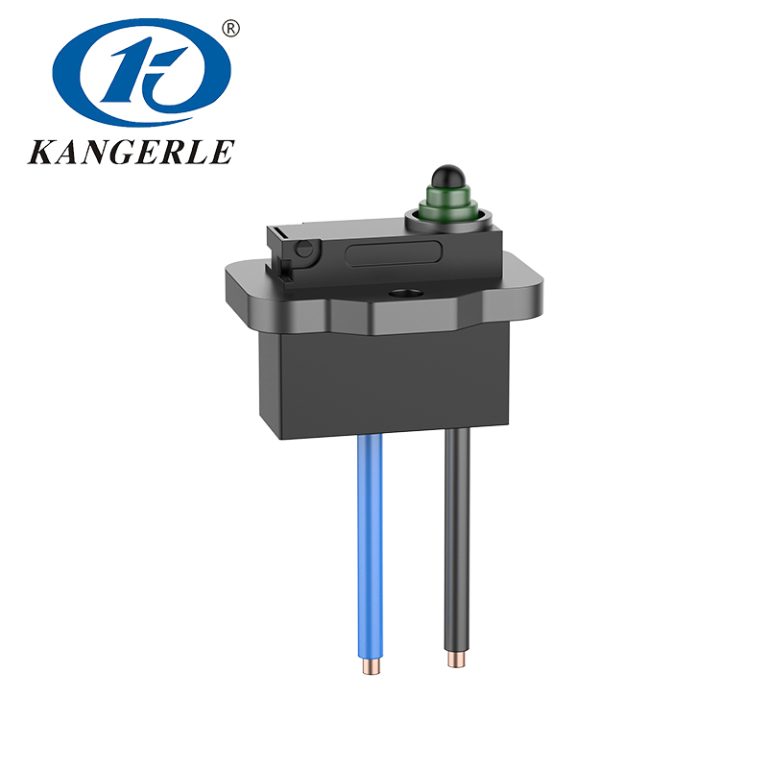
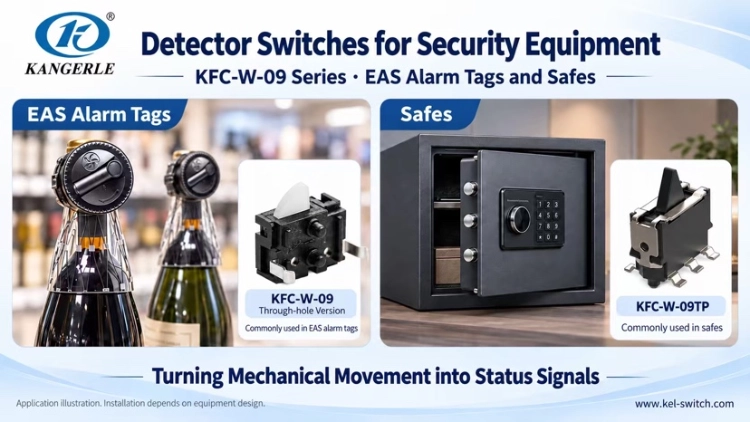
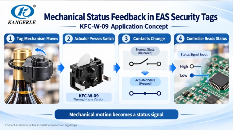
KANGERLE‘s KFC-W-09 pin-terminal version is commonly used in electronic article surveillance (EAS) alarm tags and security hard tags, while KFC-W-09TP is used in safes. These applications illustrate what to check when selecting and installing a detector switch.
Define the Exact Position You Need to Detect
Before choosing a switch, ask what the equipment needs to confirm. Is a cover open? Is a latch fully engaged? Has a moving mechanism returned to its home position? When that component moves, it presses or releases the switch, changing the contact state that the controller reads.
The switching point matters. If the switch activates before a latch is completely engaged, the system could report “closed” too early. Position the actuator so it responds at the mechanical state you actually need to verify.
How Is a Detector Switch Different From a Motion Sensor?
A mechanical detector switch checks the position of a particular component. A passive infrared (PIR) or radar sensor detects activity or presence within an area. Both may be used in the same security system, but they serve different purposes and are not interchangeable.
KFC-W-09 in EAS Alarm Tags and Security Hard Tags
Retail anti-theft tags combine a mechanical locking mechanism with electronic circuitry. The KFC-W-09 detector switch page introduces the pin-terminal series used in this type of application. Inside a suitable tag design, movement of the mechanism can operate the switch, allowing the circuit to recognize engagement, release, or tampering. Which state is detected depends on the tag design; electronic identification and alarm functions are handled by other circuits.
During sampling, repeatedly engage, release, and partially engage the tag. Check whether the signal remains stable after latching and whether the switch returns properly when released. In compact mechanisms, alignment errors or excessive pressing can cause unreliable results.
KFC-W-09TP in Safes
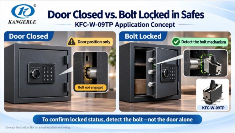
KFC-W-09TP provides a mechanical-position signal to a safe’s control circuit. Depending on the design, it may detect the door, locking bolt, or another moving part.
A closed door is not necessarily a locked door. If the equipment must confirm that the bolt is fully engaged, the switch should respond to a component that actually reflects bolt position, rather than door closure alone. Defining this requirement early helps determine mounting direction, travel, and wiring.
Reference Specifications for Selection
KANGERLE security application materials list the following reference configuration for KFC-W-09 and KFC-W-09TP: DC 30 V, 0.1 A rated load; SPST-NO (normally open) contacts; 50 ± 25 gf operating force; −10°C to +60°C operating temperature; and an electrical life of at least 50,000 operations.
Check whether the mechanism can provide enough actuation force, whether the operating temperature fits the installation, and whether the contacts suit the actual electrical load. Even where specifications are similar, verify each model’s terminals, dimensions, and mounting arrangement separately. These values are application references; use the applicable model-specific datasheet and test conditions for final approval.
Other Security Equipment Applications
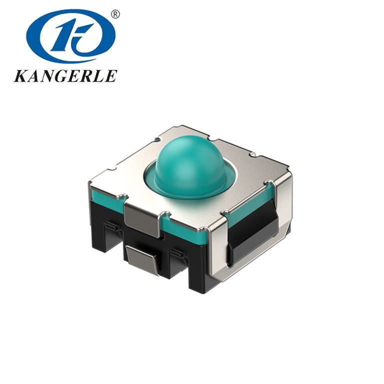
KANGERLE also lists KFC-V-111 for fingerprint-lock mechanisms, KFC-V-206KT detector switches and KCD3-11L rocker switches for carbon monoxide detector equipment, and KEL-A002 push-button switches for access-control systems. These switches support mechanical-state detection or user controls; fingerprint recognition and gas sensing are performed by other modules.
For additional form factors, review the W-series detector-switch options and the broader KANGERLE detector-switch range.
Cover Closed but No Signal? Check the Assembly First
If the controller does not recognize a closed cover or engaged latch, check whether the moving mechanism actually operates the switch. Focus on three areas.
Actuator alignment. An off-center contact surface or sideways force may prevent consistent operation. Confirm that the pressing point and movement direction match the product drawing.
Bracket stability. A thin bracket may flex during closing, while loose fasteners can allow the switch to shift. Observe both the bracket and the switch as the actual mechanism closes.
Loose and tight assembly conditions. Manufacturing tolerances change the final contact position. A loose assembly may not press far enough to trigger the switch; a tight one may press too far. Test both extremes instead of relying on one nominal prototype.
Allow Enough Travel Without Over-Pressing
Insufficient travel may leave the switch unactuated. Excessive travel can apply unnecessary force and potentially damage it. An independent mechanical stop should let the switch complete its required movement without absorbing the closing impact of a door or latch.
During adjustment, record where the electrical signal changes and where the mechanism finally stops. Compare the distance between these positions with the approved drawing. If loose assemblies fail to actuate while tight assemblies over-press, adjust the contact surface, bracket, or stop together.
Operating force also matters. In a lightweight cover or compact security tag, switch resistance can affect how smoothly the mechanism closes. Evaluate the switch in the real assembly and confirm that it returns normally after release.
Stable Signals Also Depend on the Contacts and Circuit
Choose the Contact Arrangement for the Circuit
Normally open (NO) and normally closed (NC) describe the contact state when the switch is not actuated. Whether the equipment displays “open” or “closed” depends on installation and how the controller interprets the signal. Check the terminal diagram for the exact model before wiring.
Also determine what happens if a wire breaks or a connector becomes loose. An NC contact may support certain fault-detection designs, but it does not make the complete system fail-safe by itself.
Check Suitability for Low-Current Inputs
Provide the actual voltage, current, AC or DC supply, and load type. A controller input with very low current is different from switching a larger load. Do not rely only on the maximum rating; confirm whether the contact has a minimum recommended switching load.
Distinguish Contact Bounce From Mechanical Instability
Contacts can briefly open and close several times during switching—known as contact bounce. Loose brackets, partial engagement, or insufficient travel can also cause repeated signal changes.
Observe the electrical response during slow, fast, and partially engaged operation. Hardware or software debounce can filter brief transitions, but excessive filtering delays genuine status updates. Mechanical looseness still requires a mechanical correction.
Evaluate Life and Protection Under Actual Conditions
An indoor safe, a retail security tag, and equipment near an exterior entrance face different conditions. Consider temperature, dust, moisture, vibration, and cleaning methods. Housing seams, actuator openings, and cable entries may also admit contaminants.
Estimate how many operating cycles the device will experience, including maintenance. Mechanical life describes cycling under specified conditions, while electrical life also depends on the switched load. Compare test conditions along with the stated cycle count.
A sticking latch or loosened bracket can affect detection after extended use. Include the complete mechanism in endurance testing, not just the switch.
Prepare These Details Before Requesting Samples
When asking about KFC-W-09 for an EAS tag or KFC-W-09TP for a safe, provide:
- Detected position:The cover, latch, locking bolt, or other part and the exact position to confirm.
- Mounting structure:Available space, fixing method, drawings, and direction of applied force.
- Actuation requirements:Available travel, allowable operating force, and mechanical stop.
- Circuit:Required NO/NC behavior, terminals, voltage, current, and load type.
- Environment:Temperature, dust, moisture, vibration, and expected operating cycles.
- Fault response:The required behavior when open, partially engaged, disconnected, or reporting an abnormal signal.
Mounting drawings and prototype photos can help identify interference or alignment problems before testing.
Verify Reliability in the Assembled Prototype
Test samples with production-like brackets and moving parts connected to the intended controller input. This confirms both mechanical actuation and how the equipment interprets the resulting signal.
- Check reliable actuation, release, and return in loose and tight assemblies.
- Close the mechanism slowly and quickly; include partial latch engagement and light bracket loading.
- Record missed detections, false detections, repeated transitions, and controller response delays.
- Repeat the checks after planned cycling and environmental exposure.
Before testing, define what counts as a missed or false detection and the acceptable response time. Keep the part number, drawing revision, important dimensions, and test conditions with the results so that design changes can be compared fairly.
For network-connected equipment, the NIST IoT cybersecurity program offers broader system-security guidance; it does not qualify a mechanical detector switch.
Frequently Asked Questions
Does a Higher Switch Life Rating Guarantee a More Reliable Device?
No. Alignment, bracket stability, actual circuit load, and environment also affect detection. Life ratings are one selection factor, and the complete assembly still requires testing.
Can the Latch Be Designed Before Selecting the Detector Switch?
It is better to design them together. Switch dimensions, force, and travel affect the latch and bracket geometry. Early coordination helps prevent missed actuation and excessive pressing.
Can a Detector Switch Be Used Directly as a Safety Interlock?
Not automatically. Detecting a mechanical position does not establish suitability or certification for safety-interlock use. Check applicable component and system requirements separately.
Match the Switch to the Equipment
Reliable position detection depends on the switch, actuator travel, mounting structure, and electrical input working together. Define the position to confirm, select suitable operating force and travel, and verify performance in the finished assembly.
Zhejiang Kangerle Electronics offers KFC-W-09, KFC-W-09TP, and related detector-switch solutions for security equipment. Share your application, installation drawing, and circuit requirements to discuss suitable samples. The KFC-W-09 product page is a useful starting point for reviewing the series before final model confirmation.