

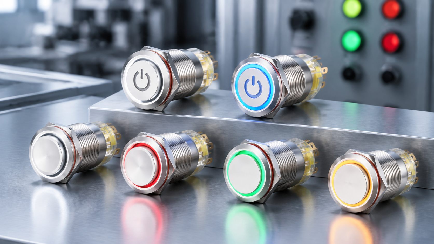
An illuminated metal push button switch combines a mechanical control contact with a built-in light. That small change gives a control panel a clear status signal while keeping the familiar push action. The same idea appears in machine controls, power equipment, automotive panels, medical devices, communication equipment, and outdoor enclosures.
The wiring becomes straightforward once the two electrical paths are separated. The switch contacts handle the control circuit. The LED ring has its own supply terminals. This guide explains the working principle, terminal names, wiring choices, and checks that help prevent a wrong connection.
What Is an Illuminated Metal Push Button Switch
A metal push button switch uses a metal bezel and actuator around a spring or latching mechanism. Inside, contacts open or close when the button moves. An illuminated version adds an LED, often arranged as a ring around the actuator. The light can show that power is present, that a machine is running, or that a command has been accepted.
In a waterproof metal push button switch, the front seal and mounting arrangement help limit dust and water entry. Protection claims depend on the exact construction, wiring, installation, and test conditions. A panel cutout, gasket, nut, and cable entry all affect the finished result.
How the Two Circuits Work
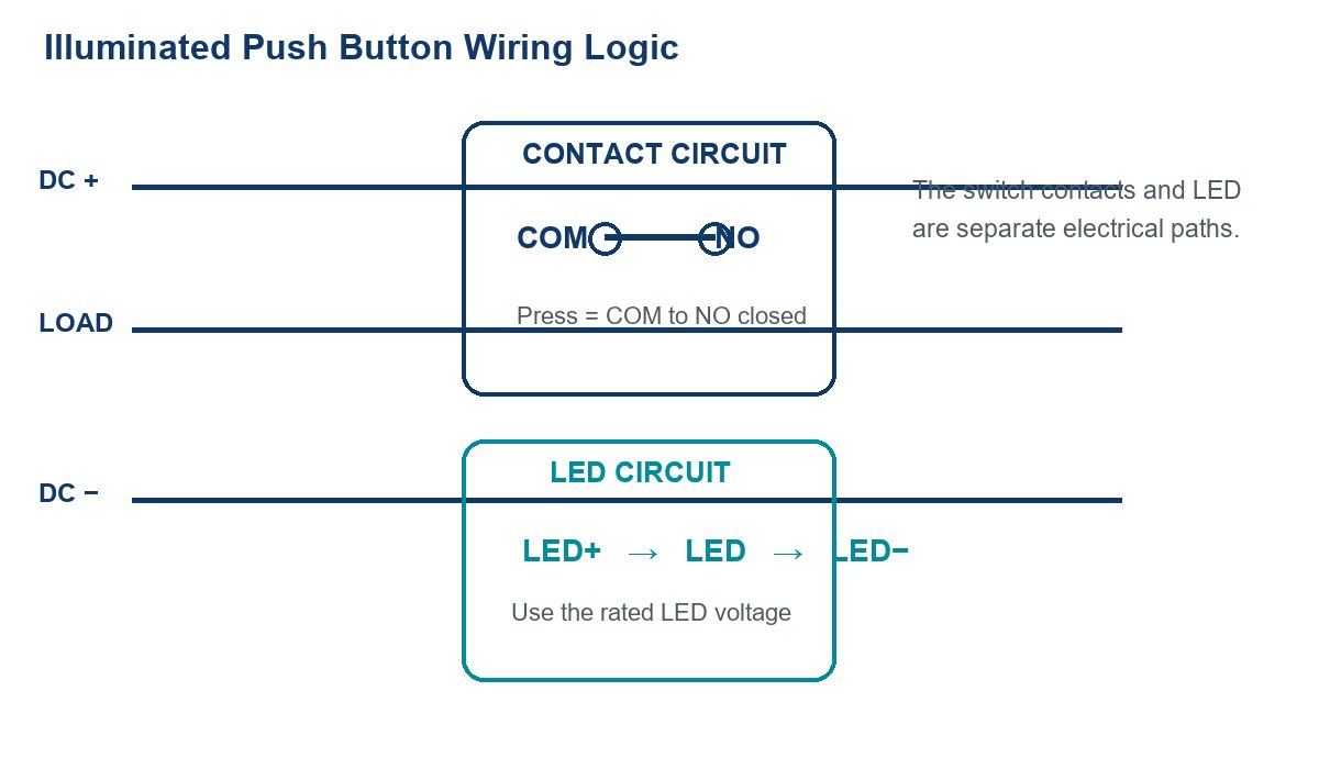
The cleanest way to read an illuminated push button switch wiring diagram is to treat the product as two circuits in one body. The contact circuit moves a load or sends an input signal. The LED circuit produces light. They may use the same supply, but they do not have the same terminals or job.
When the button is pressed, a normally open path can close between COM and NO. A normally closed path can open between COM and NC. The LED can stay on all the time, light only when the button is pressed, or follow the status of a relay or controller. That behavior comes from the wiring around the switch.
Terminal Names You Need to Know
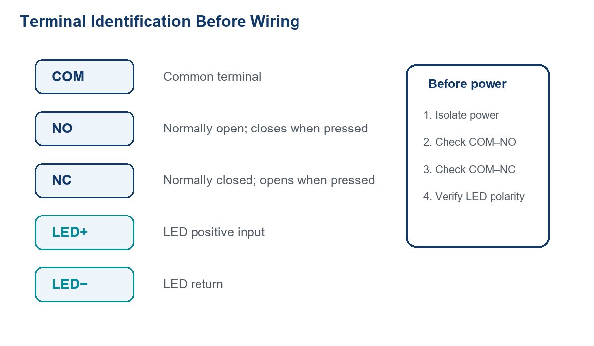
Terminal labels vary across suppliers and constructions, so the drawing for the selected switch should control the final connection. The table below describes the common terms used in a 5 pin push button switch with LED.
| Terminal | Meaning | Typical use |
| COM | Common contact | Input or shared contact point |
| NO | Normally open | Closes when the button is pressed |
| NC | Normally closed | Opens when the button is pressed |
| LED+ / A1 | LED positive input | Connect to the rated LED supply |
| LED− / A2 | LED return | Connect to the matching return path |
Momentary and Latching Operation
A momentary illuminated push button switch changes state only while the actuator is held. It suits a start command, reset input, test button, door release, or PLC signal. Releasing the button returns the contact to its normal state.
A latching illuminated push button switch keeps its state after the press. A second press changes it back. This style suits maintained power selection and equipment enable functions. The LED may show the button position, the presence of supply voltage, or the actual load state, depending on which circuit feeds it.
How to Wire an LED Metal Push Button Switch
Before wiring, isolate the power source and read the terminal marking. Confirm whether the part uses COM, NO, and NC, then identify the two LED terminals. Check the LED voltage, current limits, contact rating, and whether the switch is momentary or latching.
For a basic momentary NO circuit, connect the control supply to COM and connect NO to the load or controller input. The other side of the load returns to the supply reference. For a stop or interlock function, the NC contact may be used so the control path opens when the button is pressed.
Wire the indicator separately. Connect LED+ to the specified positive supply and LED− to the matching return. A 12 V LED version must not be treated as a 24 V or 110 V version. Some products include the needed current limiting inside the LED assembly; others require the circuit shown in the product drawing.
A reliable test sequence is simple: use a continuity meter with power isolated, identify COM–NO and COM–NC, verify LED polarity, apply the correct LED supply, and test the final load only after the indicator and contact behavior are confirmed.
Common Wiring Choices
The same illuminated metal push button switch can perform different jobs depending on the circuit around it.
- Momentary NO control: press to send a start or trigger signal, then release to stop the signal.
- NC stop logic: use the normally closed path when the control system should open the circuit during a stop command.
- LED always on: feed the LED from the equipment supply so the ring shows that power is available.
- LED load status: connect the LED to a relay or controller output so it lights only when the controlled device is active.
Selecting a 19 mm IP67 Metal Push Button
The 19 mm IP67 metal push button switch is ideal for industrial control panels and machines that need to be durable, perform reliably, and show status clearly. Designed with stainless steel case and ring LED lighting, this small size switch is applicable in the machine controls, automation systems, vehicles and electrical equipment that is used outdoors.
It works with 1NO and 2NO contacts, giving people the opportunity to choose between various control circuits. Built-in LED ring gives visual feedback about the power status of your machine or the status of the whole system. It is possible to use it at various voltages and colors.
Being waterproof with IP67 rating, this push button switch provides protection from dust and moisture if properly installed. With 19 mm mounting diameter, metal structure, and various operation modes, this switch is good when it comes to long lasting use and proper functioning. Before purchasing, it is necessary to check the contact type, LED voltage, installation needs and other things.
Common Mistakes to Avoid
- Connecting LED+ and LED− to COM, NO, or NC without checking the drawing.
- Applying the wrong LED voltage because the button looks the same as another version.
- Assuming every five-terminal switch uses the same pin order.
- Treating a momentary switch as a latching switch during control-panel design.
- Relying on the front seal alone while leaving the rear wiring entry exposed.
- Testing or changing the connection while the circuit is energized.
Why Work With ZHEJIANG KANGERLE ELECTRONICS CO LTD
ZHEJIANG KANGERLE ELECTRONICS CO LTD , founded in 1993, provides switches and connectors for foreign equipment manufacturers and engineers. The range of products comprises metal push button switches, tact switches, micro switches, rocker switches, household appliance switches, car switches, and connectors. The company also provides information about its services in the fields of OEM and ODM that could go through the stages of engineering, tooling, sample, evaluation, and manufacturing.
For a buyer, the practical value is access to a broader switch range and a technical route for matching the contact function, LED supply, mounting size, operating force, and environmental conditions. Quality and certification statements should still be checked against the exact series, model, and current supporting documents. General company information is available on the official company website and contact page for project discussions.
Conclusion
An illuminated metal push button switch becomes easier to wire when the contact circuit and LED circuit are treated as separate paths. Identify COM, NO, NC, LED+, and LED−, match the LED supply to the selected version, and test the contacts before connecting the final load. For a waterproof or 19 mm panel switch, installation details and the exact product drawing matter as much as the front appearance.
FAQs About Illuminated Metal Push Button Switch Wiring
These short answers cover the wiring questions engineers and installers usually check before powering the switch.
How does an illuminated push button switch work?
It combines a mechanical contact circuit with a separate LED circuit. Pressing the actuator changes COM, NO, or NC, while the LED lights according to the supply and control path connected to its own terminals.
How do you wire a 5 pin push button switch with LED?
Identify COM, NO, NC, LED+, and LED− from the product drawing. Wire the load through the contact terminals, then connect the LED terminals to their rated supply and return.
Does an LED push button switch have polarity?
Many LED assemblies use a positive and negative terminal. Check the marking and the specification because polarity and internal protection can vary by version.
What is the difference between a momentary and latching switch?
A momentary switch returns when released. A latching switch stays in its new state until it is pressed again. The choice depends on whether the control signal should be temporary or maintained.