

A marine hatch switch may have shelter from spray without being free of moisture. There may still be condensation at the mechanism, vibration through the mounting and salt deposited on an exposed connection. For a closed-hatch signal, linkage limit or cover check, the waterproof micro switch needs to suit both the electrical duty and the movement at that mounting point.
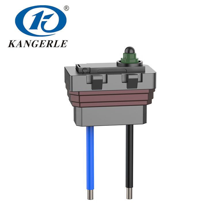
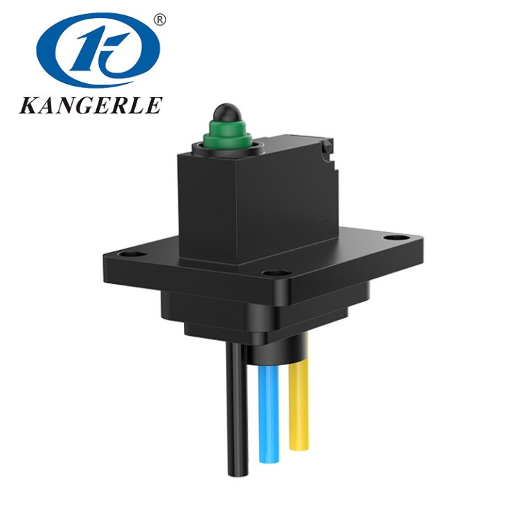
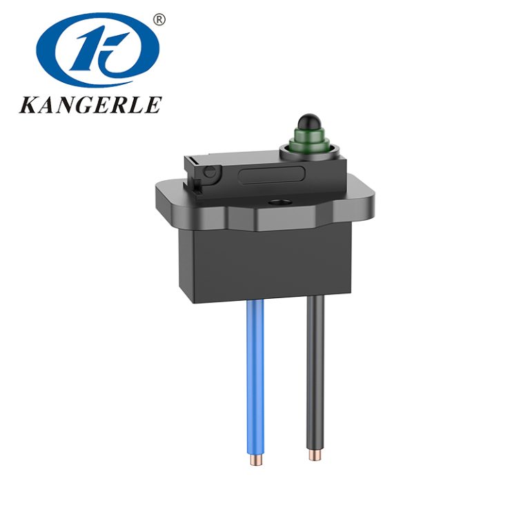
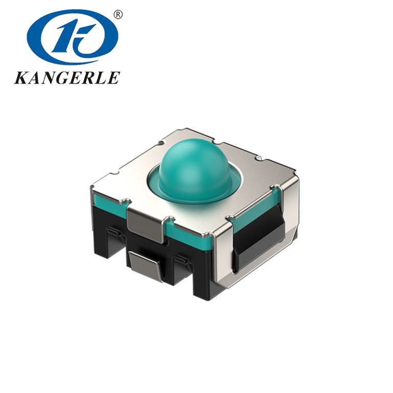
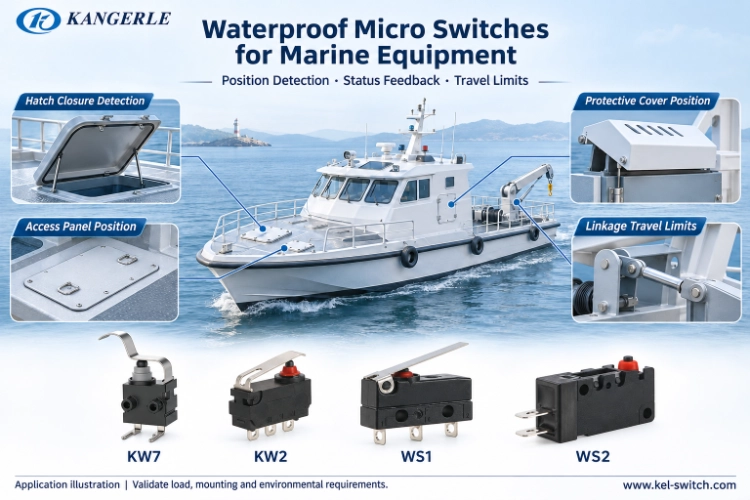
KANGERLE offers KW7, KW2, WS1 and WS2 waterproof micro switches among its precision switch products. There are differences in body size and actuators as well as load rating. Treat them as candidates for evaluation: the wired part, its bracket and the finished marine equipment still need to pass the project’s tests.
What Marine Conditions Require from a Switch
Follow Water Entry Paths and Check Corrosion Exposure
A control inside a protected housing faces different conditions from a fitting on an exposed deck. Establish where water can reach the switch before choosing the component.
- At the actuator: look for direct spray reaching the moving part.
- Inside the housing: account for condensation collecting around the mechanism.
- Along the cable: trace any route towards a terminal with an incomplete seal. The body seal cannot protect an unsealed connection elsewhere.
Continue along that route through the cable entry and strain relief, then the mounting hardware and drainage. For exposed terminals, fasteners or metal that will encounter salt, specify a separate corrosion test. An ingress rating leaves that exposure to be assessed.
Keep Actuation Stable under Vibration
With intermittent switching, the bracket deserves inspection as well as the contacts. It may have worked loose under vibration, changing where the mechanism reaches the actuator. Watch for side loading during the press, and allow for the combined part and assembly tolerances when fixing the support.
Identify the circuit connected to the contacts. A controller input, resistive load and inductive load impose different demands. A switch suitable for position feedback is not automatically rated to interrupt a motor’s starting current.
Waterproof Micro Switch Applications in Marine Equipment
Hatch and Access-Panel Position Detection
A closed hatch moves the actuator far enough to change the contact state at the controller. Its actual position depends on hinge play and gasket compression. Give the mechanism the travel allowance needed for those variations when setting the switch position.
Der KW7 Wasserdichter Mikroschalter is worth evaluating for a small, low-current detection assembly. The series is rated 0.1 A at 12 V DC with operating force ≤300 gf. Its lever contact point and cable exit need to be located on the final installation drawing before the bracket position is accepted.
Travel Limits in Moving Mechanisms
For a moving cover or linkage, including a winch-related mechanism, the useful signal may be the end of travel. Set the operating point ahead of the mechanical hard stop. That leaves the controller or independent protection system to respond; the actuator should not become the stop.
KW2 and WS1 can be evaluated against the available space and required actuator arrangement. Check the lever and mounting dimensions on the exact part drawing. Component selection remains one part of the equipment’s overall safety assessment.
Equipment Status and Auxiliary Controls
A service latch or protective cover may need a simple status contact. The same applies to a linkage in a pump assembly, where the switch reports position. That signal rating does not establish permission to switch power to the pump motor.
WS2 can be considered where more installation space is available and its verified rating matches the circuit. Enough room for the body is only the first check. There must also be access to fasten it and finish the wiring.
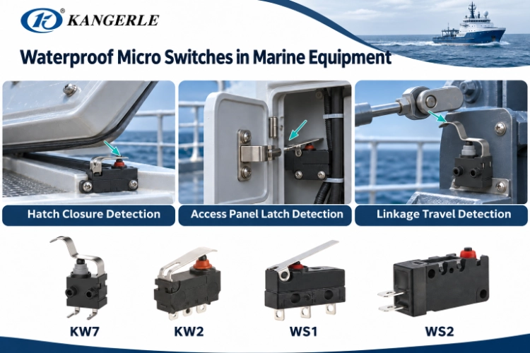
Comparing KW7, KW2, WS1 and WS2
FP is the free position; OP is the operating position. Read the millimetre dimensions from the reference points indicated on that part’s drawing. Keep that drawing beside the load and force figures during comparison. The values below describe series characteristics, so the ordered part still needs its own confirmed specification.
KW7 for Compact Low-Current Detection
The KW7 series is designed for compact, low-current position detection. The series figures provide a starting point for selection:
Use FP 11.9 mm and OP 11.2 ± 0.3 mm when comparing the series positions with the drawing. KW7 requires operating force ≤300 gf and is rated 0.1 A at 12 V DC. The series runs from −40°C to +85°C, with 100,000 electrical cycles and 300,000 mechanical cycles stated for their separate test duties. Protection is IP67 after wire soldering under the specified sealing conditions.
Next, put the lever and cable route into the installation drawing. The available space has to accommodate the actual operating point, not just the outline of the body.
KW2 for Different Mounting and DC Load Requirements
Der KW2 Wasserdichter Mikroschalter has a different load rating from KW7. The KW2 family and its mounting-hole version share these series figures, although their mounting outlines differ:
In KW2’s series figures, the 3 A at 12 V DC rating accompanies FP of 3.8 mm and OP of 3.0 ± 0.5 mm. Operating force is ≤150 gf. The temperature range is −40°C to +85°C, and the separate life values are 100,000 electrical cycles and 500,000 mechanical cycles. As with KW7, IP67 applies after wire soldering and under the specified conditions.
The higher current figure won’t settle a KW2 choice by itself. The circuit must suit that rating, and the mechanism must reach the actuator in the intended direction.
WS1 for Medium-Sized Mechanisms
Der WS1 Wasserdichter Mikroschalter can be evaluated where medium-sized mounting space is available. Its series figures include FP of 9.2 mm, OP of 8.4 ± 0.5 mm and operating force of ≤350 gf. For temperature, the series range is −40°C to +105°C. Its life figures refer to separate tests: 10,000 cycles under electrical duty and 1,000,000 for mechanical operation. The IP67 condition is after wire soldering.
Obtain the approved voltage and AC/DC classification before accepting a particular 10 A version. A lever-operated assembly needs a check through the whole approach and the movement left after operation. If the support lets vibration or an unsuitable force bend the lever, its switching point can move.
WS2 Where More Installation Space Is Available
The larger WS2 Series can be evaluated for applications with more installation space. Put its series FP of 18.6 mm and OP of 17.4 ± 0.5 mm against your installation drawing, along with operating force ≤250 gf. For temperature, the series is specified from −40°C to +105°C. Its stated electrical life is 10,000 cycles; mechanical life is 1,000,000 cycles. These values retain their separate test conditions. IP67 applies after wire soldering with the specified sealing conditions.
Before accepting a 10 A configuration, obtain its approved voltage and AC/DC rating. For motor switching, check the contact form and the actual load covered by the test conditions. Include the wired connections in the space allowed for installation.
Checks Before Approving a Marine Waterproof Micro Switch
IP67 Protection and Cable Sealing
With all four families, IP67 is specified after wire soldering. Inspect that finished condition, particularly the sealed solder joints and the cable where it bends out of the body. Dust protection and temporary immersion are the duties addressed by IP67 under its defined tests.
Do not infer permanent underwater use from IP67. Salt exposure and pressure washing also need separate assessment. Specify the exposure the installed assembly actually has to withstand. The series information does not give a full model number with a particular immersion depth, duration or water temperature. Use the specified exposure to agree those details for the completed wired part.
Electrical Load and Actuator Compatibility
For the circuit comparison, include running voltage and current as well as starting or surge current. Add contact form and any inductive load. KW7 and KW2 have different series ratings—0.1 A at 12 V DC and 3 A at 12 V DC respectively. A proposed WS1 or WS2 configuration needs its voltage and AC/DC classification confirmed for that duty.
At either end of the assembly tolerance, compare the mechanism’s movement with FP, OP and the total permitted travel. Too little movement can miss a signal. Too much movement after actuation can damage the actuator. The installed switch needs to work at both extremes of the permitted assembly variation.
Service Life and Maintenance
Mechanical life covers repeated movement of the actuator. Electrical life covers contact operation under the specified load. A part that still clicks may already have contact problems, so the noise alone cannot establish its electrical condition.
Keep the test conditions beside the cycle figures when assessing the actual circuit load and working environment. Service life and replacement depend on that installation and its condition, rather than the catalogue figure or age alone.
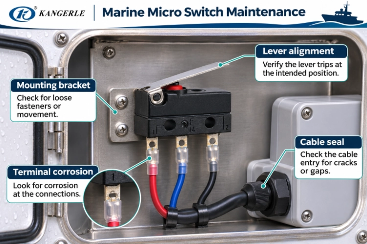
- Connections: inspect for corrosion.
- Bracket: check for looseness or movement.
- Sealing: look for damage at the protected joints.
- Trigger point: compare the point where the mechanism operates the switch with the intended position.
Sourcing and Validation Before Production
Test Samples in the Intended Mechanism
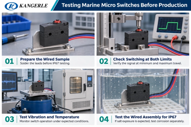
- Fit samples to the production bracket and cable arrangement.
- Check dimensions and contact response at the minimum expected actuation position.
- Repeat at the maximum position, checking movement and contact response in the same assembly.
- Have mechanical and electrical engineers review that assembled sample together.
Run the vibration and temperature tests required for the equipment’s expected environment. Where salt exposure is expected, add a corrosion test and examine the exposed terminals afterwards. Use these tests to assess the complete proposed installation.
Confirm Custom Parts with Drawings and Samples
KANGERLE can discuss terminal forms, actuators, operating force, body dimensions and application requirements. A change to a lever or cable route may affect both clearance and sealing. Replacement and custom configurations therefore need drawing review and sample approval.
Send the mounting drawing to KANGERLE with the direction of actuation marked. Include the voltage and load, contact form, wiring, force and travel requirements, plus details of condensation, spray or salt exposure. This allows a discussion of KW7, KW2, WS1 or WS2 for the assembly, and agreement on sample tests before ordering.
Häufig gestellte Fragen
Is IP67 Enough for Marine Equipment?
IP67 is not a salt-corrosion or permanent-immersion qualification. The cable sealing and finished installation still need assessment for the conditions at the mounting point.
Can a Waterproof Micro Switch Control a Boat Pump or Winch Directly?
It can provide position or limit feedback. For the motor power circuit, obtain a rating covering the real voltage, starting current and inductive load. Depending on that duty, a controller or appropriately rated relay may be needed.
What Should an OEM Buyer Include in an Enquiry?
Send the complete part number with your load, contact form, force and travel requirements. Include the installation drawing and cable termination, then describe the working environment. These details let the supplier discuss a configuration and the samples needed to assess it.