
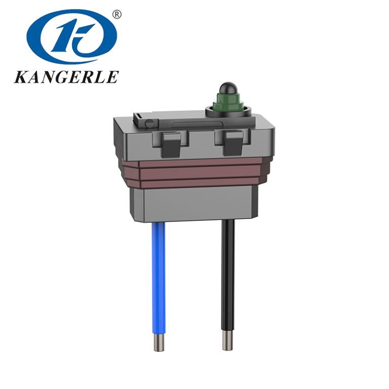
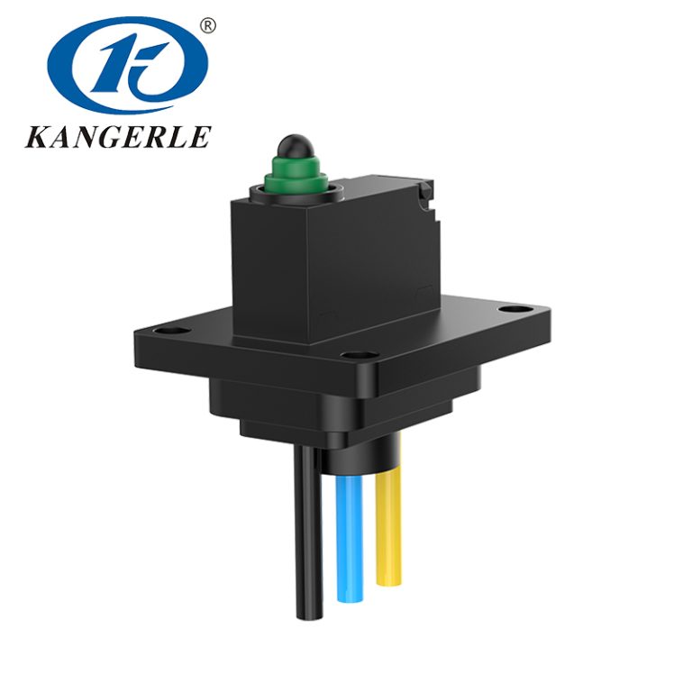
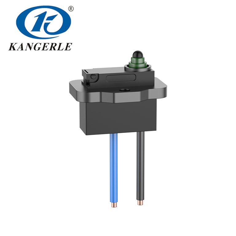

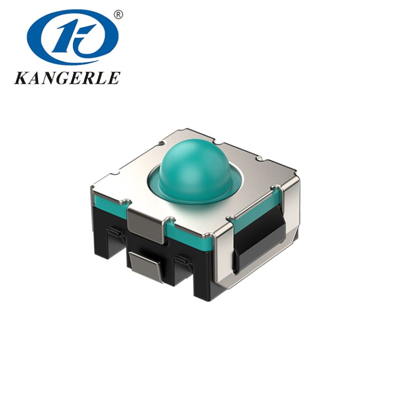
Although an automotive tactile switch may occupy only a few square millimeters on a PCB, it directly affects the driver’s perception of button quality. If the button feel is vague, overly sensitive, or becomes unresponsive after repeated use, the in-vehicle operating experience will be significantly degraded even when the electronic design itself has no issue.
Therefore, selecting an automotive tactile switch cannot be based on mounting dimensions alone. Electrical load, the operating-force curve, travel, keycap structure, mounting tolerances, service life, and water and dust protection requirements must be considered as an integrated system. This article explains selection methods for applications including steering-wheel controls, center consoles, power-window modules, overhead control panels, and trunk-release buttons.
Core Selection Parameters for Automotive Tactile Switches
These parameters are interrelated. For example, changing the actuator height affects the fit between the keycap and the switch; increasing the operating force can reduce accidental activation but also increases the user’s pressing effort; adopting a sealed construction may affect product height, cost, and button feel.
| Параметр | Items to Confirm | Common Design Risks |
|---|---|---|
| Rated Current and Voltage | Actual operating conditions at the controller input, including transient voltage and test current | Using a signal-type tactile switch to directly carry a motor or lamp load |
| PCB Pads | Pad layout, switch outline, terminal orientation, and placement tolerance | Considering only the switch outline dimensions and ignoring the PCB pad design |
| Overall Height | Overall height from the PCB to the keycap, initial clearance, and actuator tolerance | The switch remains preloaded for an extended period, or the button has excessive free travel |
| Оперативная сила | User pressing feel, button lever ratio, vibration, and accidental-activation risk | Selecting only from the datasheet value without testing the finished-button feel |
| Путешествовать | Target feel, button movement distance, and mechanical-stop position | The housing blocks the button prematurely or permits excessive pressing |
| Механическая жизнь | Expected number of operations over the vehicle service life and the design margin | Directly comparing life data obtained under different test conditions |
| Контактное сопротивление | Controller detection threshold and low-current signal margin | Unstable signals after contamination or contact aging |
| Protection Rating | Moisture, dust, cleaning process, and degree of PCB exposure | Assuming that the entire control module is fully sealed because an IP-rated switch is used |
| Mounting and Packaging | SMT process, coplanarity, tape-and-reel quantity, and reflow-soldering limits | Placement offset, component tilt, or an incompatible soldering process |
| Validation Testing | Force-displacement curve, vibration, temperature and humidity, and complete-button testing | Approving the switch only from samples or the catalog without installed validation |
How to Select Automotive Tactile Switches by Application
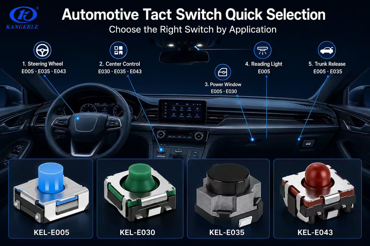
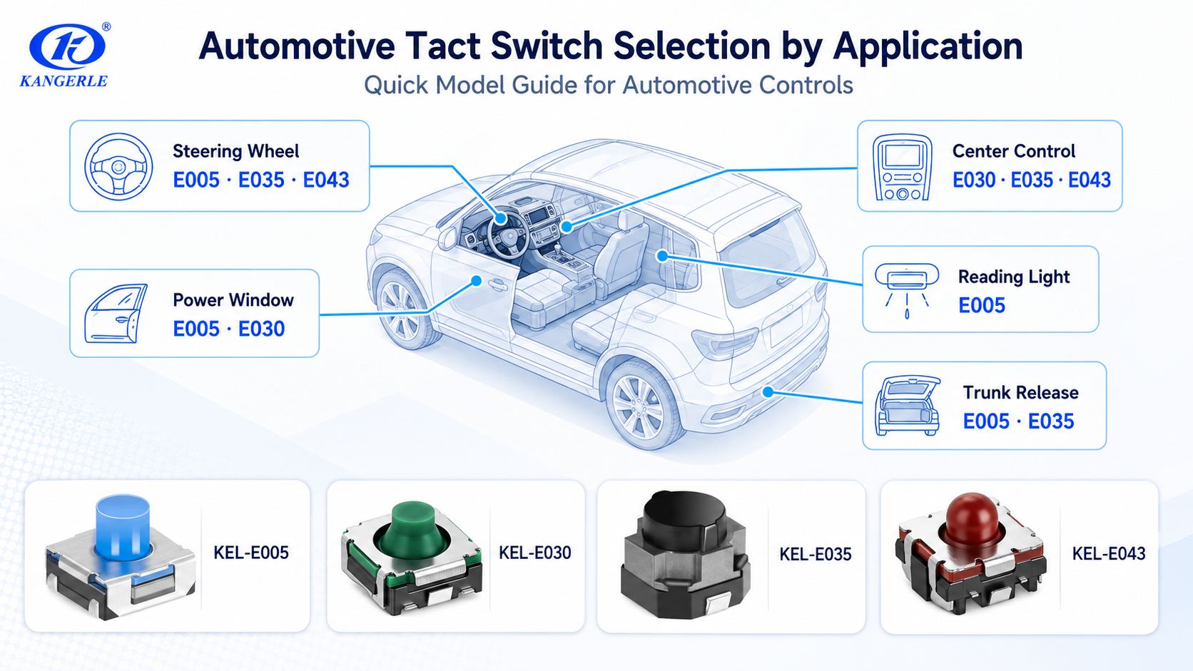
The overall feel of the various buttons in a vehicle should be coordinated, but this does not mean that the same switch must be used in every position. The following sections start from the actual usage of different buttons and progressively narrow the range of suitable KEL-E series models.
Steering-Wheel Buttons
Steering-wheel buttons are usually operated while the vehicle is moving. Drivers often rely on touch rather than looking down, so the buttons need clear, stable, and consistent feedback. At the same time, road vibration and hand contact should not cause accidental activation.
For initial selection, an operating-force range of 250–400 gf can be evaluated first and then tested with the actual button structure. Multiple buttons, light guides, and electronic components are usually concentrated on one side of the steering wheel, so compact switch dimensions make layout easier.
The following models may be prioritized:
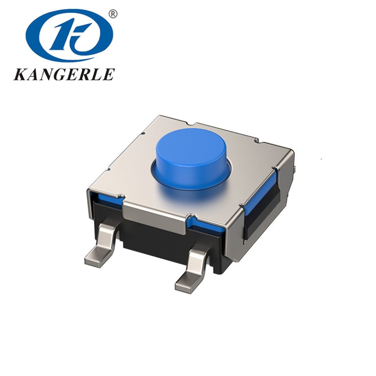
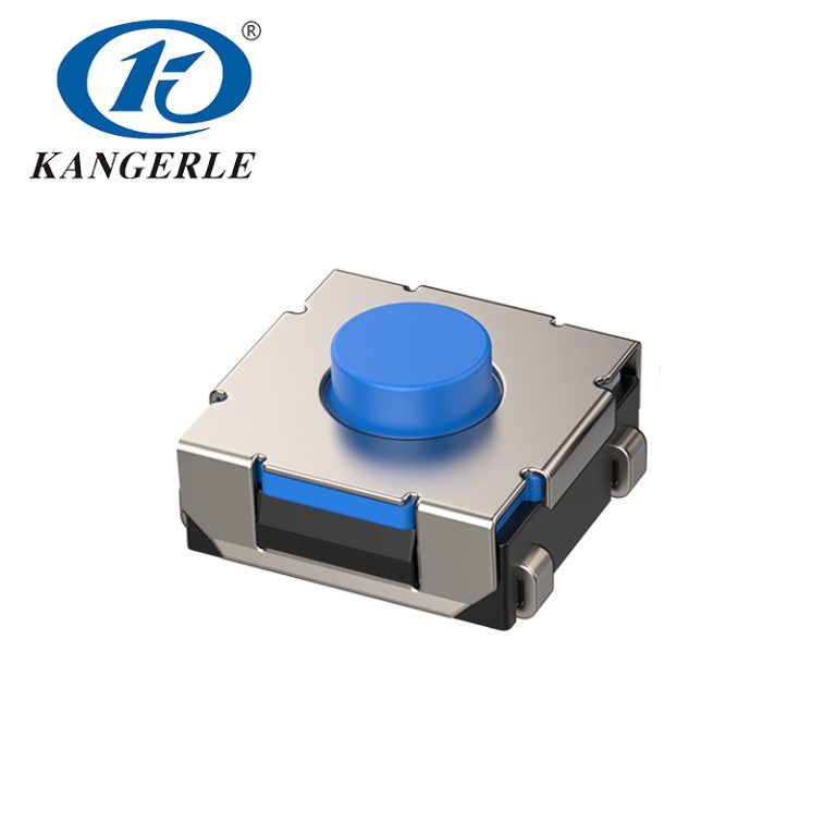
- КЕЛ-Е005 / KEL-E006: Compact construction, IP67 protection, and operating-force options of 180, 250, 350, or 400 gf. These are currently the most established automotive series in terms of stability and shipment performance.
- КЕЛ-Е042: Outline dimensions of 5.3 × 5.4 mm, travel of approximately 0.7 mm, and operating-force options of 180, 350, or 500 gf.
- КЕЛ-Е043-39: Suitable for designs requiring compact 5.3 × 5.4 mm dimensions and a low height of 3.85 mm.
- КЕЛ-Е046: The same basic dimensions are available with operating forces of 180, 300, or 380 gf, making it easier to adjust the feel of different buttons.
Steering-wheel buttons should also be tested at corner positions. For larger plastic rocker buttons or multidirectional buttons, the actual force application point may be offset from the switch center. Even when the switch is installed in the correct position, the feel may still be inconsistent at different locations.
Center-Console and Instrument-Panel Buttons
Center-console buttons include in-vehicle controls for climate settings, menus, audio, driving modes, and other functions. Their button surfaces are usually larger than steering-wheel buttons, so a longer travel or more pronounced pressing feedback can be used.
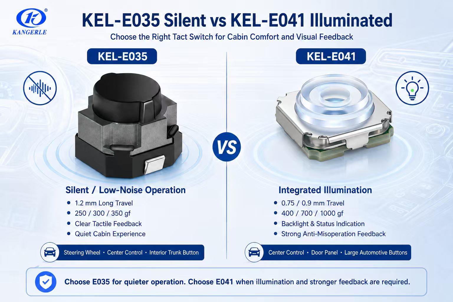
КЕЛ-Е035 is a silent, low-noise tactile switch with approximately 1.2 mm travel and operating-force options of 250, 300, or 350 gf. It combines longer travel, clear feedback, and quiet operation, making it suitable for center-console, instrument-panel, and steering-wheel buttons in vehicles where a quiet cabin experience is important.
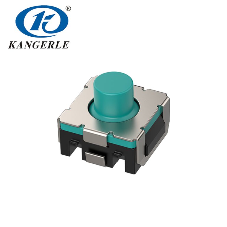
When a shorter but distinct pressing action is required, KEL-E030 may be considered. It has approximately 0.75 mm travel, operating-force options of 180, 300, or 380 gf, and a catalog mechanical life of 100,000–200,000 operations. It is suitable for interior control modules in which protection is provided by the panel or housing.
Multiple closely spaced buttons on the same panel should be tested as a complete system. Differences in keycap width, light-guide position, or support ribs can produce different final button feels even when the same switch model is used.
Power-Window and Door Control Modules
Power-window buttons are usually installed in door trim panels, where moisture, dust, and vibration require particular attention. The tactile switch is responsible only for sending a low-current control signal; the window motor is driven by a power device or control module, and the tactile switch must not directly carry the motor current.
For larger rocker buttons, especially when the mechanical structure provides lever amplification, a switch with a higher operating force may be selected. Options include the silent KEL-E035 at 250–350 gf, KEL-E037 at approximately 680 gf, and the illuminated KEL-E041 at 400, 700, or 1000 gf.
КЕЛ-Е041 combines button actuation with light indication, making it suitable for door and center-console panels that require backlighting, status indication, or position identification. In the actual design, the lighting circuit, light-transmitting keycap structure, and thermal conditions of the complete unit should all be confirmed.
However, a high-operating-force model should not be selected simply because it appears “more robust.” Pairing a small button with a 700 or 1000 gf switch may feel too stiff and cause user fatigue. A high operating force is more valuable only when the button is large, a lever structure is present, or stronger resistance to accidental activation is required.
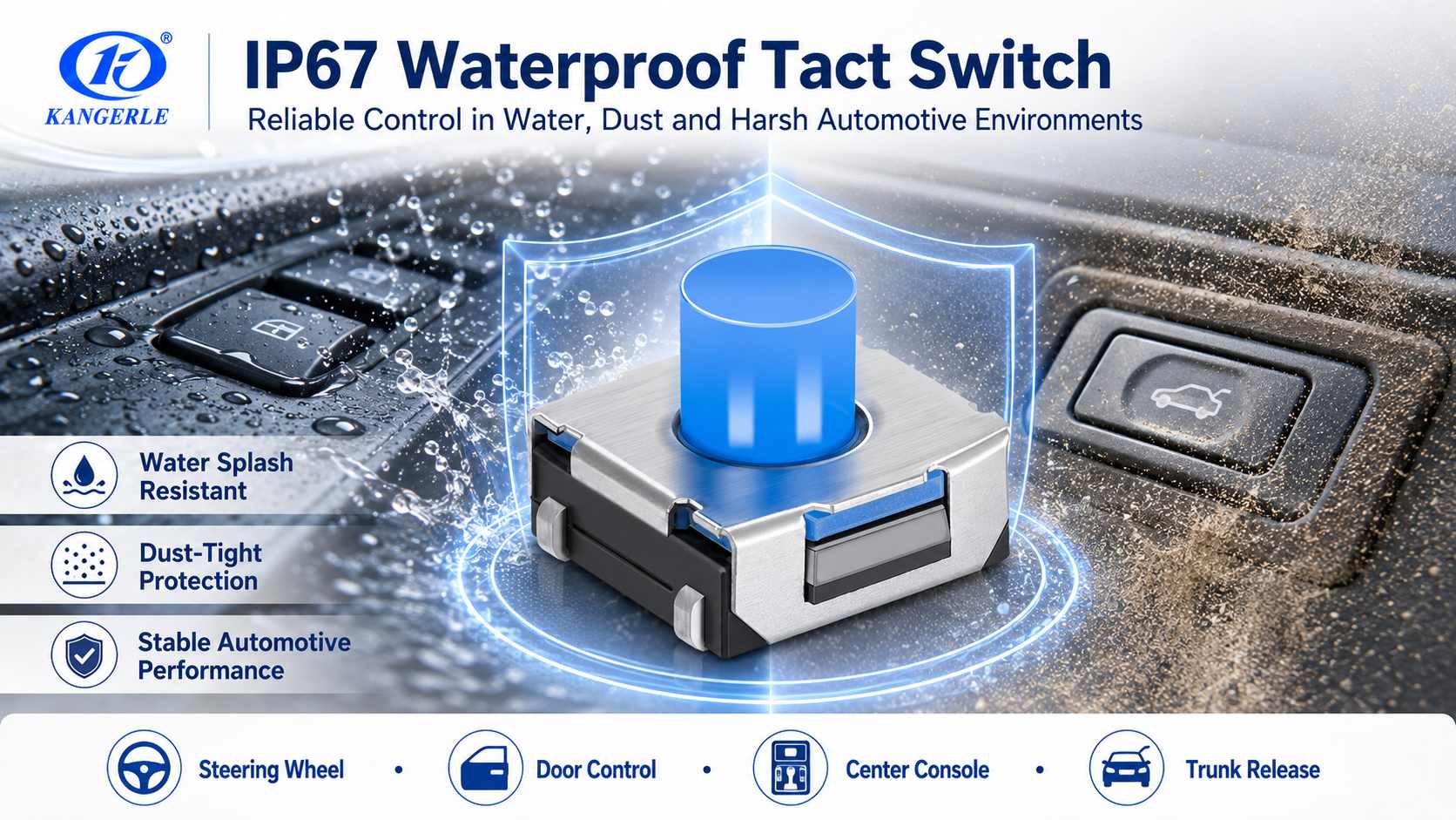
If moisture may enter the PCB area, priority can be given to evaluating the IP67-rated KEL-E005 or KEL-E006, together with a coordinated design for the housing seal, drainage path, and connector sealing. An IP67 switch protects only the component itself and cannot replace sealing of the entire door module.
Interior Dome Lights and Overhead Consoles
An overhead console may include buttons for reading lamps, roof functions, emergency calls, and the sunroof. Users normally have to raise a hand to operate them, so excessive pressing force will noticeably reduce comfort.
A compact switch with a medium operating force is usually a suitable starting point. KEL-E005 and KEL-E006 have outline dimensions of approximately 6.2 × 6.2 mm, IP67 protection, operating-force options of 180, 250, 350, and 400 gf, and multiple height options. KEL-E042 and KEL-E043-39 are smaller at 5.3 × 5.4 mm, with operating-force options of 180, 350, or 500 gf.
The keycap should be able to return freely under conditions including gravity, high in-vehicle temperatures, and plastic aging. The restoring force of the tactile switch itself must not be relied upon to solve decorative-button sticking or structural interference.
Trunk and Tailgate Release Buttons
A trunk-release button needs a distinct pressing action because the consequences of accidentally opening the trunk are more serious than adjusting the volume once by mistake. Buttons installed outside the vehicle or near an edge may also be exposed to rain, car-wash water, dust, and temperature cycling.
For locations outside the vehicle or along the tailgate edge that may be exposed to rain and car-wash water, priority can be given to evaluating the IP67-rated KEL-E005 or KEL-E006. Both products are available in multiple heights, travels, and operating forces, allowing them to work with different keycaps and waterproof structures.
For interior tailgate buttons or larger release buttons, KEL-E035 can provide silent operation and more pronounced button travel. КЕЛ-Е030, KEL-E043-39, or КЕЛ-Е043-43 is more suitable for interior modules in which protection is provided by the housing. An independent mechanical stop is still required to prevent all external force from acting directly on the switch dome and solder joints during forceful pressing.
Recommended Automotive Models: Stable, Silent, and Illuminated Solutions
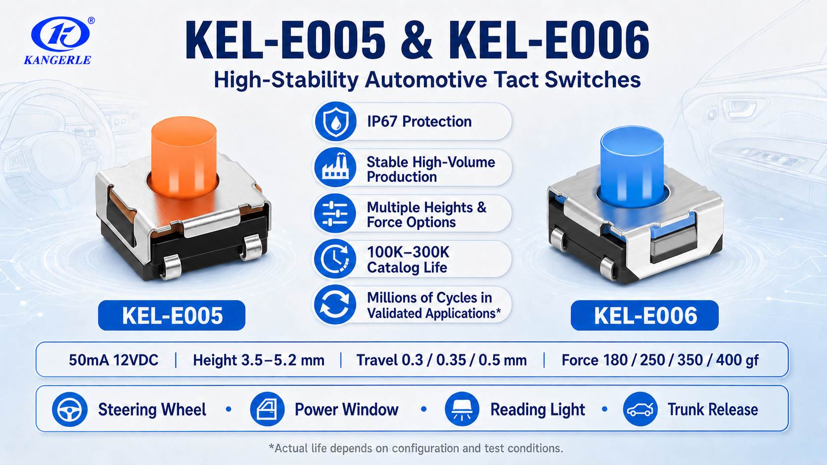
Based on the mass-production and shipment performance of current automotive projects, KEL-E005 and KEL-E006 are presently the automotive tactile-switch series with the most stable performance and the highest shipment volume. They offer IP67 protection and multiple height, travel, and operating-force options, making them suitable for high-frequency buttons or buttons with demanding environmental requirements, including steering-wheel controls, reading lamps, power windows, and tailgate release.
The standard mechanical life listed in the product catalog is 100,000–300,000 operations. In mature solutions where the load, operating force, travel, button structure, and test conditions are matched and validated for a specific project, the actual life of KEL-E005 and KEL-E006 can reach several million operations. Test conditions should also be stated on the official website or in project materials, and final acceptance should be based on approved drawings and complete-system validation results.
If a project places greater emphasis on a quiet cabin experience, the KEL-E035 silent tactile switch may be selected. Its approximately 1.2 mm long travel reduces operating noise while retaining clear pressing feedback. If the button also requires backlighting or status indication, the illuminated KEL-E041 tactile switch may be selected, with an appropriate operating force chosen from 400, 700, and 1000 gf according to button size and lever structure.
KEL-E Automotive Tactile Switch Model Comparison
The KEL-E series includes compact sealed switches, long-travel models, high-operating-force models, and low-height models for high-density automotive control modules. The 2026 automotive product range covers applications including steering wheels, center-control panels, reading lamps, power windows, and trunk release.
| Модель | Outline Dimensions and Nominal Height | Путешествовать | Оперативная сила | Механическая жизнь | Recommended Selection Applications |
|---|---|---|---|---|---|
| КЕЛ-Е005 | 6.2 × 6.2 mm; height 3.5–5.2 mm | 0.3/0.35/0.5 mm | 180/250/350/400 gf | Catalog: 100,000–300,000 operations; validated mature solutions can reach several million operations | IP67; high stability and shipment volume; suitable for steering wheels, dome lights, windows, and tailgates |
| КЕЛ-Е006 | 6.2 × 6.2 mm; height 3.5–5.2 mm | 0.3/0.35/0.5 mm | 180/250/350/400 gf | Catalog: 100,000–300,000 operations; validated mature solutions can reach several million operations | IP67; high stability and shipment volume; suitable for high-frequency automotive buttons |
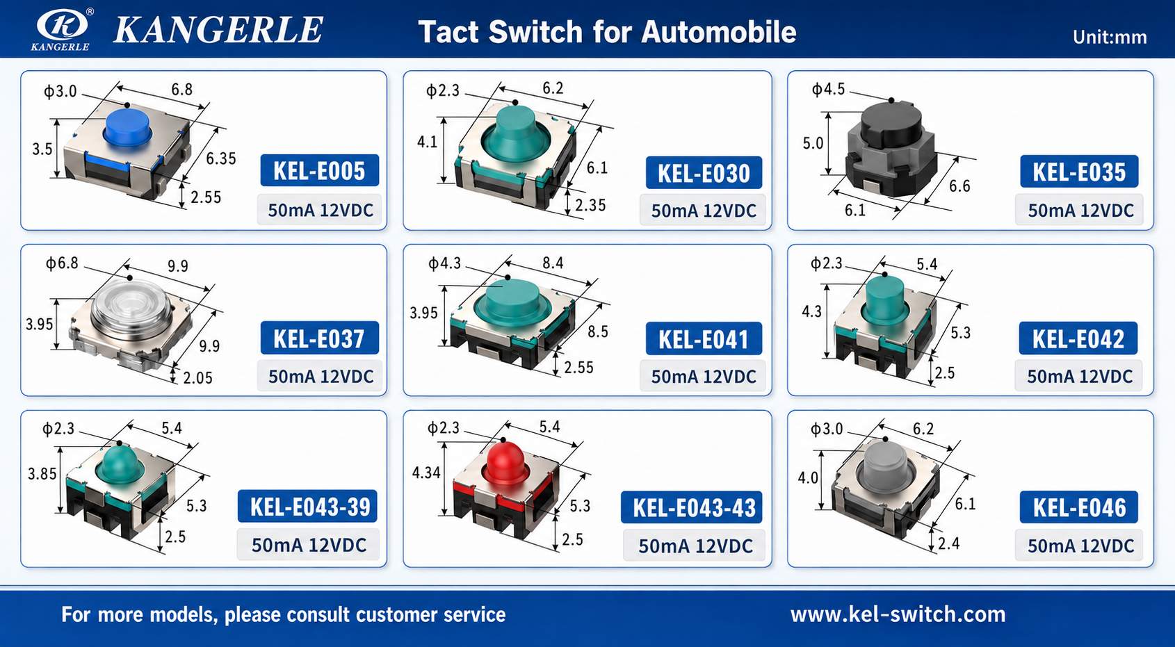
| КЕЛ-Е030 | 6.1 × 6.1 × 4.1 mm | 0.75 mm | 180/300/380 gf | 100,000–200,000 operations | Medium travel; suitable for interior buttons whose protection is provided by the panel or housing |
| КЕЛ-Е035 | 6.0 × 6.1 × 5.0 mm | 1.2 mm | 250/300/350 gf | 100,000–200,000 operations | Silent, low-noise, long travel; center-console, steering-wheel, and interior tailgate buttons |
| КЕЛ-Е037 | 9.9 × 9.9 × 3.95 mm | 0.75 mm | Approx. 680 gf | 100,000–500,000 operations | Large size and high operating force; suitable for large buttons requiring stronger resistance to accidental activation |
| КЕЛ-Е041 | 8.5 × 8.5 × 3.95 mm | 0.75/0.9 mm | 400/700/1000 gf | 100,000–500,000 operations | Illuminated; suitable for panels requiring backlighting, status indication, or stronger protection against accidental activation |
| КЕЛ-Е042 | 5.3 × 5.4 × 4.25 mm | 0,7 мм | 180/350/500 gf | 100,000–300,000 operations | Compact steering-wheel and control-panel layouts |
| КЕЛ-Е043-39 | 5.3 × 5.4 × 3.85 mm | 0,7 мм | 180/350/500 gf | 100,000–300,000 operations | Low-height, compact interior buttons |
| КЕЛ-Е043-43 | 5.3 × 5.4 × 4.35 mm | 0,7 мм | 180/350/500 gf | 100,000–300,000 operations | Compact interior buttons with a taller actuator |
| КЕЛ-Е046 | 6.1 × 6.1 × 4.0 mm | 0,7 мм | 180/300/380 gf | 100,000–200,000 operations | Multiple operating-force options on the same platform |
Note: All dimensions above are in millimeters. Height, operating force, protection rating, and life may vary by configuration. Approved drawings and project samples should be used as the basis before the PCB design is finalized.
Practical Automotive Tactile Switch Selection Process
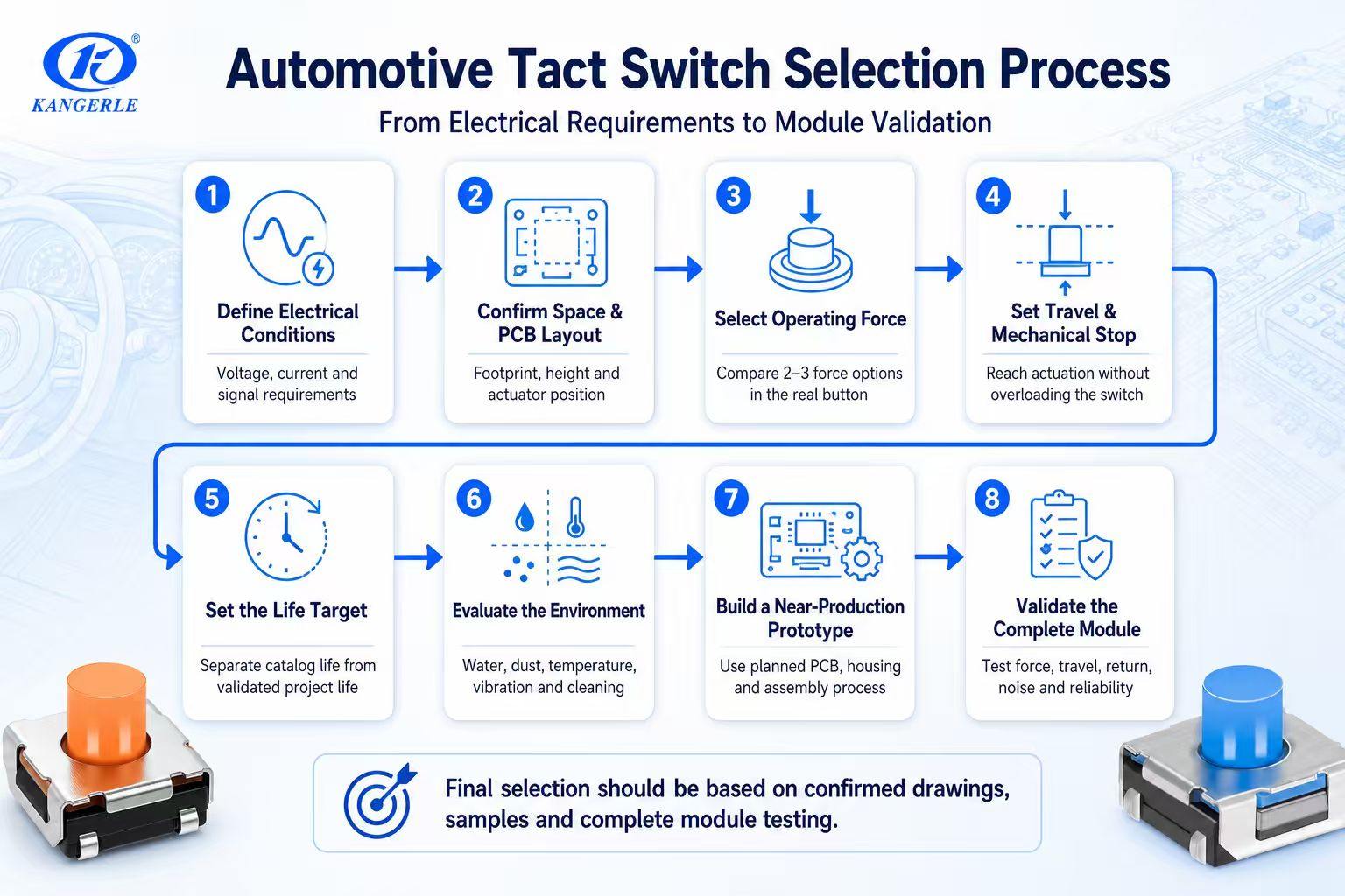
Using a structured selection process can reduce late-stage changes to the PCB, button tooling, and module housing, while also allowing purchasing and engineering teams to compare samples using the same set of criteria.
- Define the circuit conditions. Record the switch voltage, current, controller detection threshold, maximum contact resistance, and software debounce method.
- Confirm the available space. Check the PCB pads, component keep-out area, actuator center position, and permitted overall height.
- Draw the complete button structure. Mark all plastic parts, silicone parts, light guides, and the minimum and maximum clearances.
- Select two or three operating-force levels. Test with buttons that closely resemble the mass-production structure; do not make a decision based on a single value in the datasheet.
- Determine travel and mechanical stops. The button must be able to reach the electrical actuation point, but the tactile switch must not be used as the final mechanical stop.
- Calculate life based on actual use. Allow sufficient margin based on high-frequency users, repeated operation, and vehicle service life; distinguish between catalog-rated life and project-validated life.
- Evaluate the operating environment. Consider temperature, humidity, liquid splashes, dust, cleaning agents, vibration, and the PCB coating process.
- Build samples close to mass production. Use the planned PCB thickness, soldering process, button materials, and housing structure.
- Measure the performance of the assembled button. Record the actual finger pressing force, travel, sound, return action, and differences among multiple samples.
- Conduct module-level reliability testing. Perform life-cycle testing on the complete button mechanism under the applicable temperature, humidity, and vibration conditions.
For a new vehicle platform, sample testing should preferably be completed before the decorative-part tooling becomes difficult to modify. A switch that appears suitable in the datasheet may still require adjustment to actuator height or operating force after it is installed beneath the final button.
Zhejiang Kangerle Electronics: Automotive Switch Supplier
ZHEJIANG KANGERLE ELECTRONICS CO. LTD was established in 1993 and is located in Yueqing, Wenzhou. It focuses on switch research, development, and manufacturing for automotive electronics, home appliances, industrial control, security equipment, consumer electronics, and other fields. The company’s production chain covers mold manufacturing, precision stamping, injection molding, assembly, automated inspection, and component processing.
The company’s quality system is certified to ISO 9001:2015 and IATF 16949:2016. Its inspection process covers incoming materials, production processes, functional performance, appearance, and outgoing products. The laboratory can conduct tests including high- and low-temperature testing, operating-life testing, dimensional measurement, operating-force measurement, contact-resistance measurement, and material analysis.
During project development, Kangerle can provide support including switch selection, sample evaluation, drawing approval, terminal and actuator adjustment, operating-force and travel matching, pilot production, and volume supply. When an automotive control module must fit a specific PCB, button structure, or installation space, this type of project support is more important than simply selecting a standard model from the catalog.
Заключение
The right automotive tactile switch is not necessarily the model with the smallest dimensions, the highest operating force, or the longest life. It is the model that matches the circuit, PCB, keycap, and vehicle environment while avoiding unstable feel, accidental activation, and excessive mechanical stress.
It is recommended to start from the specific application and then screen models progressively according to mounting dimensions, height, operating force, travel, life, and protection rating. The final model should be determined through testing of the complete button module using the planned button structure and actual operating conditions. For KEL-E series projects, providing the PCB layout, button cross-sectional drawing, target finger pressing force, expected life, and environmental requirements will make selection and sample evaluation more direct.
Часто задаваемые вопросы
What Operating Force Is Appropriate for an Automotive Tactile Switch?
Many automotive buttons can initially be evaluated in the 250–400 gf range. This range generally provides clear feedback without making routine operation excessively strenuous. Lower operating forces are suitable for lightly pressed or frequently used buttons such as dome lights; forces above 600 gf are more suitable for larger buttons, lever structures, or controls requiring stronger resistance to accidental activation. The keycap structure can significantly change the actual finger pressing force, so testing must be performed in the actual button assembly.
Does Every Automotive Button Require an IP67 Tactile Switch?
Not necessarily. IP67 tactile switches are more suitable for positions where moisture, condensation, dust, or cleaning fluids may contact the component, such as door modules, trunk controls, and some overhead buttons or buttons close to the vehicle exterior.
For a dry, enclosed instrument-panel module, an IP67 switch may not be required if the complete-unit design and validation results permit it. However, even when the switch itself is rated IP67, the water and dust protection of the entire housing and control module must still be evaluated separately.
How Much Mechanical Life Does an Automotive Tactile Switch Require?
The life requirement depends on the actual operating frequency of the button. For example, operating a button 20 times per day for 15 years results in approximately 109,500 operations. In this case, selecting a switch rated for 200,000 or 300,000 operations provides more design margin than a 100,000-operation model.
Frequently used buttons on the steering wheel and center console generally require more life margin than service, reset, or rarely used functions. The catalog standard life of KEL-E005 and KEL-E006 is 100,000–300,000 operations. Mature automotive solutions can reach several million operations under matched load and structural conditions after project validation. The specific life should still be based on approved drawings, test conditions, and complete-system validation results.
What Is the Difference Between KEL-E043-39 and KEL-E043-43?
Both products have outline dimensions of 5.3 × 5.4 mm, travel of approximately 0.7 mm, operating-force options of 180, 350, or 500 gf, and a catalog mechanical life of 100,000–300,000 operations.
The main difference is the nominal height: KEL-E043-39 is approximately 3.85 mm and is suitable for low-height control modules; KEL-E043-43 is approximately 4.35 mm and is suitable for structures with a larger spacing between the keycap and PCB. Neither product is marked IP67 in the 2026 automotive selection materials. If a project has waterproofing requirements, priority should be given to evaluating KEL-E005 or KEL-E006.
What Information Is Required When Requesting Automotive Tactile-Switch Samples?
It is recommended to provide the target application, PCB pads, available height, keycap drawing, target operating force, desired travel, electrical load, expected life, protection requirements, operating temperature, annual usage volume, and other relevant information.
A cross-sectional drawing of the button-and-switch assembly is particularly valuable. It can be used to check actuator height, preload, overtravel, and the position of the mechanical stop before samples are installed.