
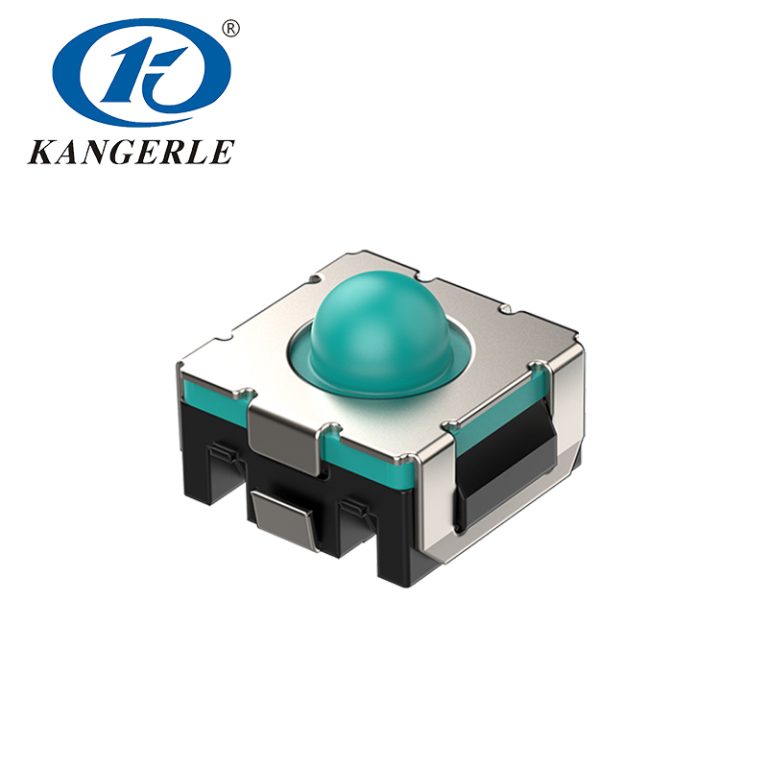
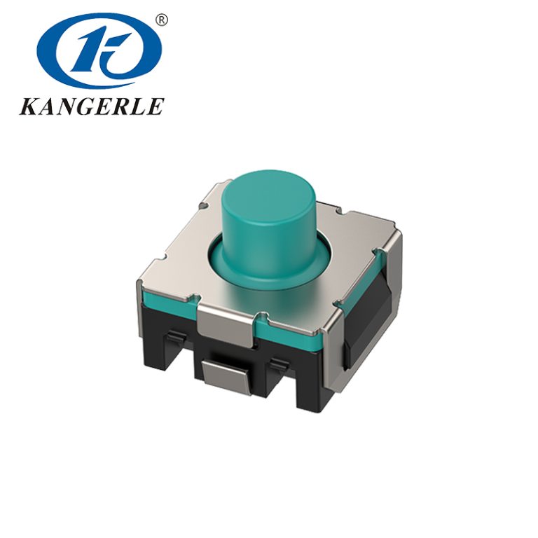
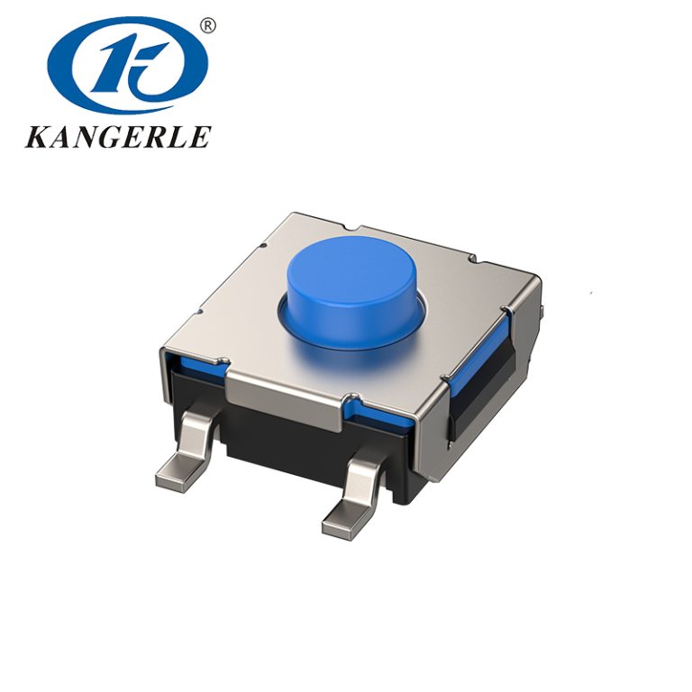
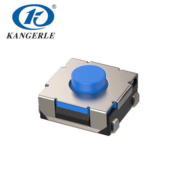
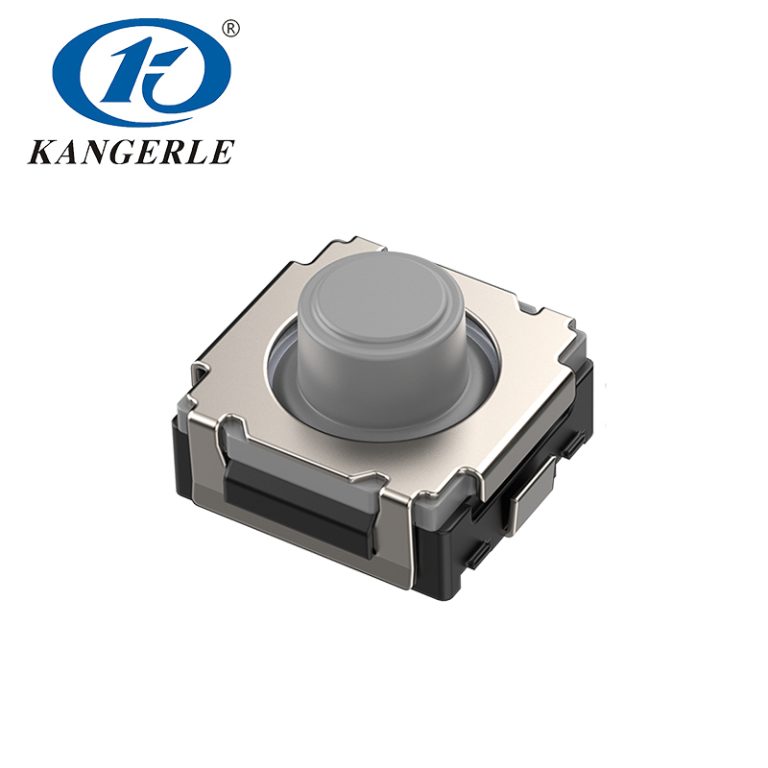
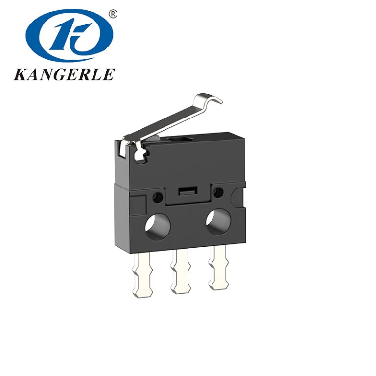
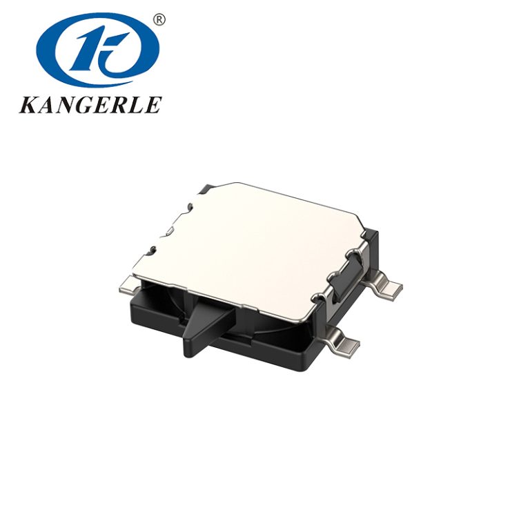
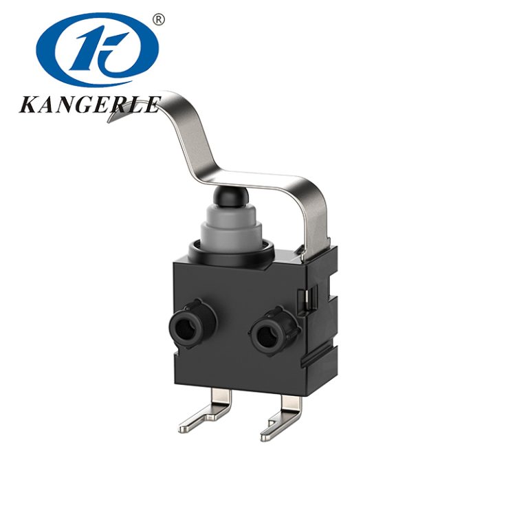
A waterproof micro switch is small, yet a poor choice can stop a conveyor, disable a charging connector, or create an unreliable safety signal. Dust, oil mist, vibration, temperature changes, and repeated impact can shorten service life.
The right waterproof micro switch must fit the circuit and moving mechanism. An IP67 label alone is not enough. Load, circuit, force, actuator, terminals, space, and cycle life also matter.
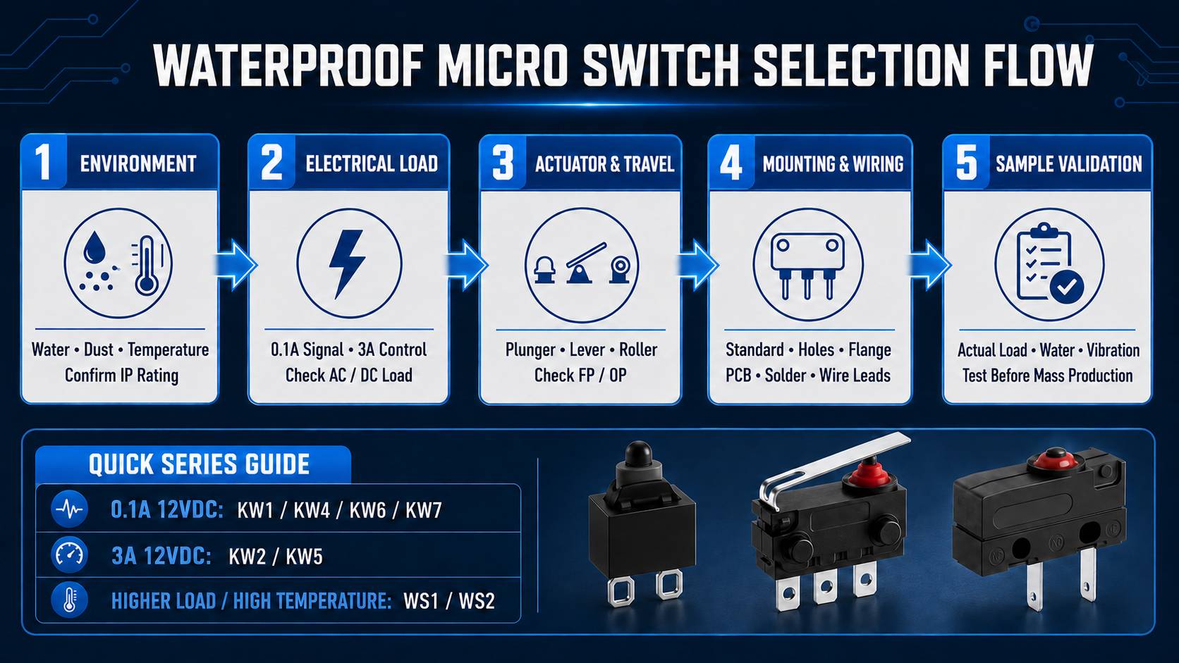
Start With the Working Environment
Begin at the installation point. A switch inside a cabinet faces different risks from one beside a wash-down nozzle or beneath a vehicle chassis.
IP67 is common in wet and dusty equipment. The first digit covers solids; the second covers water. The rating applies under defined conditions, so it does not automatically cover hot-water jets, hydraulic oil, detergent, salt spray, or permanent immersion.
Before choosing an IP67 waterproof micro switch, record:
- Direct rain, splash, condensation, dust, oil mist, or cleaning fluid
- Lowest and highest operating temperature
- Vibration and direction of impact
- Whether the actuator, terminals, and wire exit are exposed
- Required service interval and downtime cost
Pay attention to wording such as “IP67 after wiring.” A sealed housing can still lose protection through poor soldering, damaged insulation, or an unsealed cable exit.
Match the Electrical Rating to the Load
Check voltage, current, and load behavior together.
AC and DC Ratings Are Not Interchangeable
A switch rated for AC may not carry the same current in DC. DC arcs are harder to extinguish. Use the stated DC rating for a 12 V or 24 V system.
Motor, solenoid, lamp, and capacitive loads may draw inrush current far above their normal value. A 2 A motor circuit can briefly exceed that level during startup. The selected industrial micro switch needs margin for the peak.
Choose the Contact Circuit
SPST-NO, SPST-NC, and SPDT circuits serve different needs.
| الدائرة | Typical use | Signal behavior |
| SPST-NO | Counting or presence detection | Closes when actuated |
| SPST-NC | Guard doors and safety interlocks | Opens when actuated |
| SPDT | Two-state position feedback | Changes between NO and NC |
For a PLC input, stable low-current switching may matter more than high current capacity. For a motor or valve circuit, load rating and electrical life matter more.
Choose the Actuator and Operating Force
The actuator is where the machine meets the switch. A good electrical match can fail if a moving part strikes it at the wrong angle.
Pin Plunger, Lever, or Roller?
A pin plunger micro switch suits short, direct movement and accurate position detection.
A hinge lever accepts more travel and usually needs less force. It fits doors, cams, and parts with moderate position variation.
A roller lever waterproof micro switch is better for sliding parts, rotating cams, and repeated passes. The roller reduces rubbing where a plate or cam crosses the actuator many times per shift.
The mechanism should press smoothly and leave enough overtravel after the operating point. Too little travel causes missed signals. Too much may bend a lever, damage the spring, or shift the operating point. Avoid side loading on a plunger.
Operating force matters in light mechanisms. A soft latch may not reliably trigger a 150 gf switch after wear, dirt buildup, or low-temperature stiffening. Test the weakest expected force.
Check Terminals, Dimensions, and Assembly
A suitable switch can still fail if its terminals clash with the enclosure or its lever cannot reach the cam.
Solder terminals suit compact wire harnesses. PCB terminals shorten board assembly. Lead-wire versions reduce exposed connections and may simplify outdoor sealing.
Confirm body size, mounting-hole spacing, terminal direction, lever length, wire bend radius, and tool access. Leave room for strain relief. Sideways wire tension can break the seal.
Why Check FP and OP?
The catalog lists FP (free position) and OP (operating position) for each series. FP is the actuator position when no force is applied; OP is the position where the contacts change state. For example, the KW2 series has an FP of 3.8 mm and an OP of 3.0 ± 0.5 mm, while the KW1 series has an FP of 4.8 mm and an OP of 4.1 ± 0.3 mm.
The mechanism’s actual stroke must pass beyond OP while retaining a safe overtravel margin. Because models differ in body shape and actuator design, FP and OP values should not be compared without reference to the dimensional drawing. Final confirmation should come from the official specification and a physical fit test.
Compare Mechanical and Electrical Life
Mechanical life measures unloaded operations. Electrical life measures switching under stated voltage, current, and load conditions. They are not interchangeable.
A position detection switch may complete many low-current cycles, while the same mechanism wears faster with an inductive load.
For critical equipment, review:
- Electrical life at the actual load
- Mechanical life at the planned travel and force
- Contact resistance after endurance testing
- Temperature cycling and vibration data
- Relevant product and quality-system certifications
Test samples in the real assembly with production wiring, the actual cam profile, and expected contaminants.
Use the Kangerle Catalog for Initial Model Screening
The Kangerle waterproof microswitch catalog can first be screened along three main paths: 0.1 A at 12 VDC for low-current signal detection, 3 A at 12 VDC for control circuits, and 10 A-class products for higher loads. The list can then be narrowed by operating force, service life, temperature range, mounting-hole design, or flange configuration. The relevant series are marked IP67 after wiring, so sealing the wiring remains part of the finished-equipment design.
| مسلسل | الحمل المقدر | قوة العمليات | حياة Elec./Mech. |
Key Selection Points |
| KW1 | 0.1 A 12 VDC |
120 ± 30 gf | 100,000/ 300,000 |
Ultra-compact; -40 to 85°C; low-current signals, EV charging connectors, vehicle locks, and pushbutton detection |
| KW4 | 0.1 A 12 VDC |
≤150 gf | 100,000/ 300,000 |
Compact lever design; -40 to 85°C; position detection where space is limited |
| KW6 | 0.1 A 12 VDC |
≤150 gf | 100,000/ 300,000 |
Compact direct-plunger design; -40 to 85°C; precise position detection |
| KW7 | 0.1 A 12 VDC |
≤300 gf | 100,000/ 300,000 |
Compact lever model; -40 to 85°C; two-wheeler buttons, door locks, and tailgate detection |
| KW2 Mounting-hole options |
3 A 12 VDC |
≤150 gf | 100,000/ 500,000 |
Standard or mounting-hole version; -40 to 85°C; EV charging connectors and outdoor controls |
| KW5 Flange options |
3 A 12 VDC |
≤150 gf | 100,000/ 500,000 |
A/B/C flange options; -40 to 85°C; more flexible mounting |
| WS1/ WS2 |
10 A class* | ≤350/ ≤250 gf |
10,000/ 1,000,000 |
-40 to 105°C; suited to higher loads or higher-temperature environments |
Note: The exact rated voltage, contact configuration, and load type for WS1 and WS2 must be confirmed in the formal specification for the project. A “10 A class” description alone is not a substitute for validation.
How Do KW1, KW2, and KW5 Compare in a 12 V System?
For low-current signal detection where installation space is extremely limited, KW1 is a logical first choice. The catalog rates it at 0.1 A, 12 VDC, with an operating force of 120 ± 30 gf, an electrical life of 100,000 operations, and a mechanical life of 300,000 operations.
Where 3 A at 12 VDC is required, compare KW2 and KW5. Their standard operating force is no more than 150 gf, with an electrical life of 100,000 operations and a mechanical life of 500,000 operations. Choose a KW2 mounting-hole version when screw or locating-hole fixation is needed; for housing-mounted flange installation, compare the KW5 flange A, B, and C configurations.
For KW2, the catalog specifies an FP of 3.8 mm, an OP of 3.0 ± 0.5 mm, and an operating temperature of -40 to 85°C. These parameters allow engineers to check electrical capacity, trigger position, and installation geometry together instead of choosing a model merely because it looks similar.
How Can Typical Catalog Applications Be Matched Quickly?
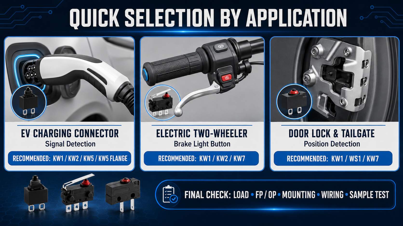
- EV charging connector signal detection: initially consider KW1, KW2, KW5, or the KW5 flange series
- Electric two-wheeler brake-light button: initially consider KW1, KW2, or KW7
- Door-lock and tailgate detection: initially consider KW1, WS1, or KW7
These are the catalog’s quick-screening routes. The same logic can be applied to industrial equipment: first determine whether the circuit is a low-current position signal, a 3 A control circuit, or a higher-load application. Then combine available space, actuation direction, and mounting method to select candidate series for sample testing.
Common Selection Mistakes
Several errors cause early failure:
- Choosing by IP rating while ignoring oil, detergent, salt, or hot water
- Using an AC rating for a DC motor circuit
- Comparing mechanical life while overlooking electrical life
- Selecting a lever exposed to side impact
- Leaving terminals and wire exits unsealed
- Skipping tests with production parts and real inrush current
The lowest unit price rarely gives the lowest operating cost when replacement requires rewiring and a line shutdown.
شركة تشجيانغ كانجيرلي للإلكترونيات المحدودة
شركة تشجيانغ كانجيرلي للإلكترونيات المحدودة is a switch supplier and manufacturer based in Wenzhou, with experience dating to the early 1990s. Its range includes micro, detector, limit, rocker, slide, tact, and push-button switches for appliances, vehicles, security equipment, industrial machines, and consumer electronics.
The company runs quality systems for general manufacturing and automotive production and supplies products with widely requested certifications. OEM and ODM support covers materials, dimensions, operating force, travel, current rating, molds, terminals, and special-environment features. This helps when a standard switch fits the circuit but not the mounting structure or wiring process.
خاتمة
Selecting the right waterproof micro switch starts with the complete application. Define water, dust, chemical, temperature, and vibration risks. Then match the AC or DC load, contact circuit, actuator, force, terminals, dimensions, and rated life.
A useful inquiry should include voltage, steady and inrush current, load type, IP rating, actuator movement, available space, terminal preference, operating temperature, and annual cycle count. These details make selection and sample testing faster.
الأسئلة الشائعة
Is an IP67 micro switch suitable for every wet industrial area?
No. An IP67 micro switch offers strong dust and water ingress protection under rated conditions, but it may not suit high-pressure wash-down, continuous immersion, steam, saltwater, or aggressive chemicals.
What is the best waterproof micro switch for a 12 V system?
The best choice depends on current, load type, circuit, force, and mounting space. A 3 A 12 V waterproof micro switch may suit a locking mechanism, but motor inrush current must be measured.
How Do KW1, KW2, and KW5 Differ?
KW1 targets 0.1 A at 12 VDC and ultra-compact installations. KW2 and KW5 are rated at 3 A, 12 VDC, with a mechanical life of 500,000 operations. KW2 offers mounting-hole versions; KW5 offers A, B, and C flanges.
What Do FP and OP Mean?
FP is the unloaded actuator position; OP is where the contacts change state. Travel must pass OP with reasonable overtravel, without over-pressing the switch.
Should a safety interlock use NO or NC contacts?
An NC circuit is common where the system should open when a guard, door, or lock leaves its safe position. The design must also account for broken wires and controller logic.
How long does an industrial waterproof micro switch last?
Service life depends on load, switching frequency, actuator travel, temperature, vibration, and contamination. Compare electrical life with mechanical life, then validate the switch in the assembly.
Can a waterproof micro switch be customized?
Yes. Common OEM and ODM changes include lever shape, terminal style, lead direction, operating force, travel, dimensions, materials, and current requirements.