
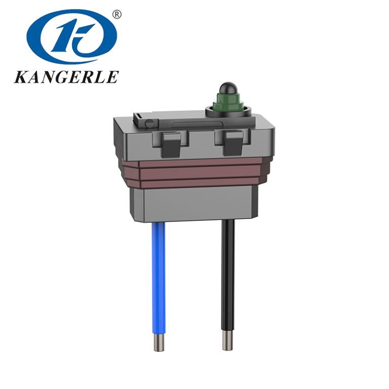
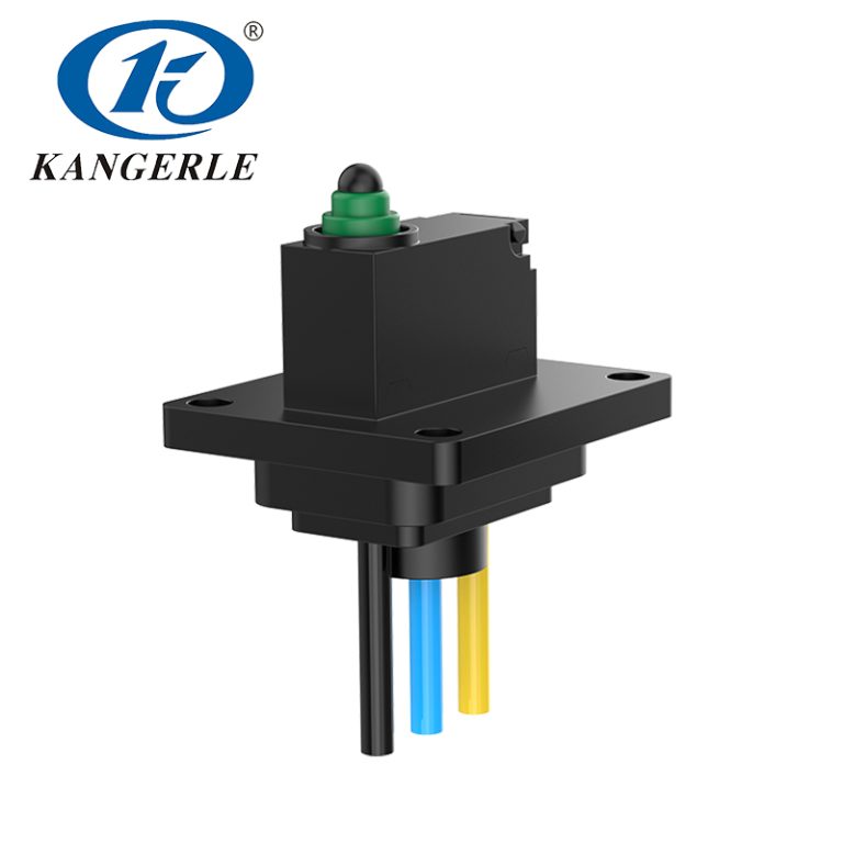
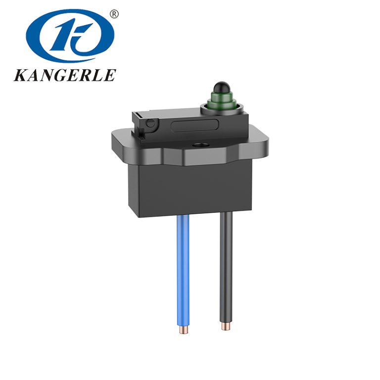

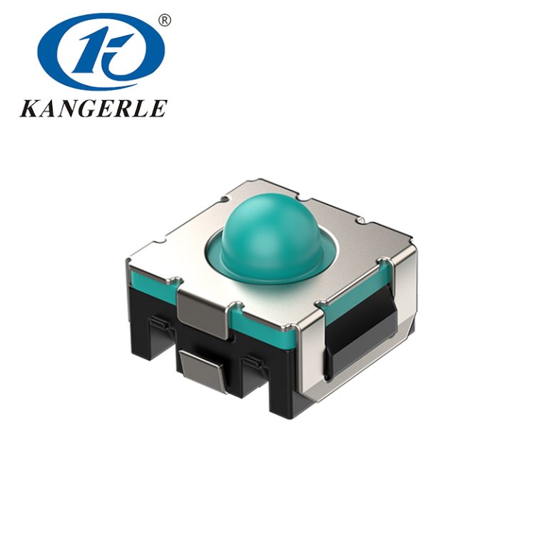
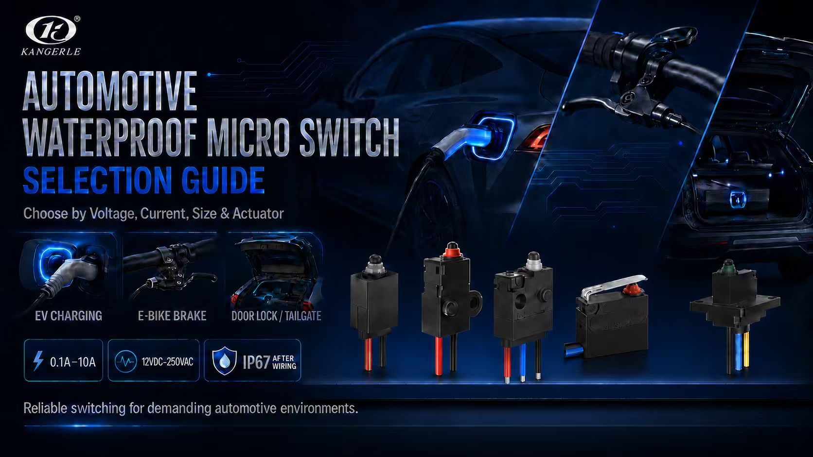
Although waterproof microswitches are small, they directly affect status feedback for EV charging connector locking, brake lamps, automotive door locks, and power tailgates. The first issues to resolve during selection are not “which series is more popular,” but two fundamental questions: What voltage and current must the circuit withstand? How large a switch can the mounting location accommodate?
Based on this selection catalog, the products can first be divided into three electrical-rating groups: 0.1A/12VDC, 3A/12VDC, and 10A/250VAC. They can then be grouped by size: KW1 and KW7 are the smallest ultra-subminiature waterproof microswitches; KW2, KW4, KW5, and KW6 are small; WS1 is a medium waterproof microswitch; and WS2 is a large waterproof microswitch. This approach is faster and less prone to selection errors than comparing multiple series one by one from the outset.
After the current, voltage, and switch size have been determined, verify the plunger or lever, operating position, operating force, contact configuration, wiring method, temperature, service life, and IP protection. Every series in the selection catalog is marked IP67 (after wiring), so the final waterproof performance also depends on the wire outlet, connector, and complete-assembly construction.
Two-step initial screening: Step 1: select the rating by operating voltage, current, and load type. Step 2: select the series by the complete envelope required for the switch body, actuator, and wires. After these two steps, perform mechanical and environmental validation.
Step 1: Select the Rating by Current, Voltage, and Load Type
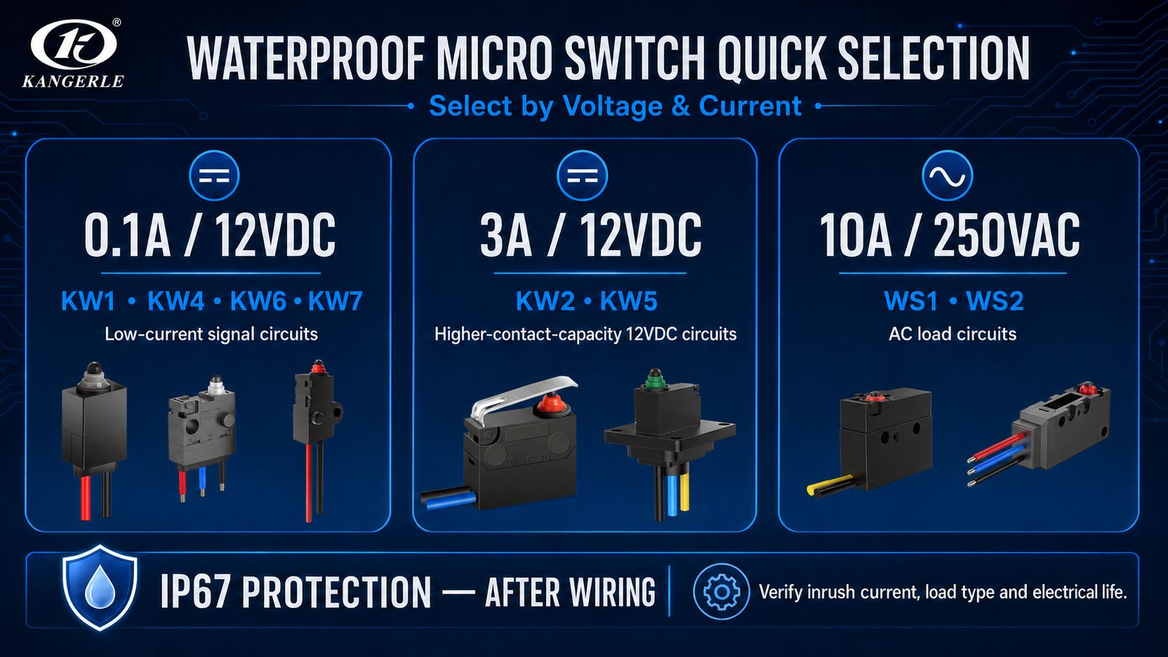
The rating is the first threshold in product selection. First confirm whether the actual operating voltage is DC or AC, and then measure the steady-state current and the peak current under the worst-case condition. Controller signal inputs, resistive sensing circuits, and loads such as motors, lamps, and coils cannot be evaluated in the same way.
| Selection-catalog rating | Applicable series | Circuits to consider first | Application note |
|---|---|---|---|
| 0.1A / 12VDC | KW1, KW4, KW6, KW7 | ECU/controller signals, position detection, low-current resistive circuits | Most compact body; a 12V system does not mean it can directly switch a high-current load |
| 3A / 12VDC | KW2, KW5, KW5 flanged cover A/B/C | Detection or control circuits requiring higher contact capacity at 12VDC | Surge current, inductive loads, and target electrical life still need to be checked |
| 10A / 250VAC | WS1, WS2 | AC loads; WS1 is medium and WS2 is large | This is an AC rating and cannot be applied directly to a 12VDC automotive motor load |
Why Can’t You Look Only at Rated Current?
- DC and AC have different arc-quenching conditions. An AC rating cannot be directly converted into a DC capability at the same current.
- Motor starting and stall currents, lamp cold-start current, and the reverse induced voltage of relay or solenoid-valve coils may all be much higher than their normal operating values.
- The ratings in the selection catalog correspond to specified test conditions. When ambient temperature, operating frequency, wiring method, or target life changes, design margin must be reserved and physical validation must be performed.
- If the microswitch only provides a status signal to the controller, a matching small-signal series should be selected first; there is no need to sacrifice size, operating force, and cost merely for a “higher current” rating.
Practical approach: Provide the operating voltage, steady-state current, peak/inrush current, load type, and number of operations per hour. If the load is a motor, lamp, or coil, it is also advisable to provide waveforms or measured data.
Step 2: Narrow the Range by Switch Size and Mounting Space
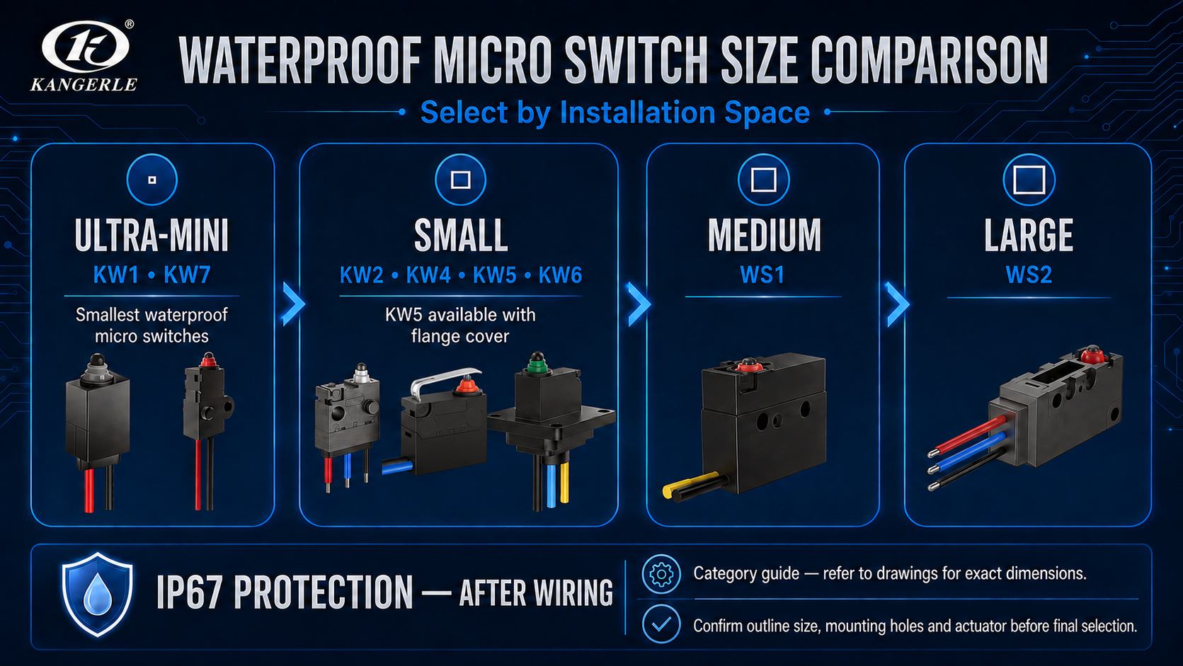
Dimensions cannot be assessed only from the length, width, and height of the switch body. What must actually be checked is the complete installation envelope: the highest point of the plunger or lever, the space required for actuation, the terminal soldering area, wire bend radius, mounting holes or flange, and the tolerances and vibration displacement of surrounding parts.
| مسلسل | Dimensions shown in catalog (mm) | Structural features | Space-selection guidance |
|---|---|---|---|
| KW1 | Approx. 8.3×5.3×7.0 | Ultra-subminiature | plunger | Together with KW7, one of the smallest waterproof microswitches |
| KW7 | Approx. 8.3×5.3×7.85; lever length approx. 13 | Ultra-subminiature | lever | Similar in size to KW1; space is required for lever movement |
| KW2 | Approx. 14.7×5.4×7.5 | Small | plunger/lever | 3A/12VDC; multiple actuation methods are available |
| KW2 with screw holes | Illustrated overall length approx. 18.5, width approx. 5.4, height approx. 6.8 | Small | with screw holes | Mounting holes facilitate screw positioning and fastening |
| KW6 | Approx. 13.3×5.3×8.95 | Small | plunger | Suitable for direct axial pressing and width-constrained structures |
| KW4 | Approx. 13.3×5.3×7.0 | Small | lever | Suitable for narrow, elongated PCB layouts and some positional tolerance |
| KW5 | Approx. 13.3×5.3×7.6 | Small | plunger/optional flange | 3A/12VDC; select a flange when a fixed mounting surface is required |
| WS1 | Approx. 19.9×6.5×9.3 | Medium | plunger | The body is larger than the small series; check the available actuation force |
| WS2 | Approx. 33×10.3×15.9 | Large | plunger | Large waterproof microswitch for mechanisms with more available space |
KW5 is a small waterproof microswitch and can be configured with a flange, making it suitable for enclosed assemblies that require a fixed mounting surface and lead wires. The approximate flange outlines shown in the selection catalog are: Type A, 18×14.5 mm; Type B, 19.8×16.8 mm; and Type C, 17.4×10.5 mm. Flange dimensions are only one part of the mounting assessment; the overall height, wire-exit direction, and wire-bending space must still be confirmed.
Dimensional note: The dimensions above are the main outline data shown in the selection-catalog illustrations and are intended for initial screening. Production design must be based on the 2D drawing, mounting datums, and tolerances of the selected complete part number; lever length, terminals, and wire-exit construction will change the total envelope.
Step 3: Verify the Actuation Method, Operating Position, and Operating Force
| Actuation/mounting form | Suitable mechanical motion | Key design points |
|---|---|---|
| Plunger type | The mechanism can press from the front along the plunger axis, with good positional repeatability | Avoid lateral force; overtravel must be provided, but the switch must not be used as a mechanical stop |
| Lever type | Rotating latches, brake levers, or mechanisms with relatively large assembly tolerances | The lever can widen the actuation range; check movement space, bending stress, and return |
| Roller lever | Cams, sliders, or continuously moving surfaces | Lower friction; verify the roller path, contact angle, and overall length |
| Flanged cover with leads | Located away from the PCB; requires a fixed mounting surface and sealed wire outlet | Verify flange-hole positions, wire length, connector, tensile force, and bend radius |
In the selection catalog, FP indicates the free position and OP indicates the operating position. Do not design the mechanism so that it merely “just reaches” OP. Reasonable overtravel must remain after actuation, and the switch must be able to return to the free position when released. Operating force must also be checked: KW1 is 120±30gf; KW2, KW4, KW5, KW6, and most KW5 flanged-cover versions are no more than 150gf; KW7 is no more than 300gf; WS1 is no more than 350gf; and WS2 is no more than 250gf.
Step 4: Confirm IP67, Temperature, Life, and Wiring
| غرض | Selection-catalog/design point | Verification focus |
|---|---|---|
| Ingress protection | All series in the selection catalog are marked IP67 (after wiring) | Verify the wiring, encapsulation, connector, and complete-assembly seams rather than testing only the bare switch |
| نطاق درجة الحرارة | KW/KW5 flanged cover: -40 to 85°C; WS1/WS2: -40 to 105°C | Select according to the highest/lowest temperature at the mounting location, thermal cycling, and material compatibility |
| العمر الكهربائي | KW series generally: 100,000 operations; WS1/WS2: 10,000 operations | Evaluate under the corresponding rated load and target operating frequency |
| العمر الميكانيكي | KW1/KW4/KW6/KW7/KW5: 300,000 operations; KW2 and most flanged covers: 500,000 operations; WS1/WS2: 1,000,000 operations | A high mechanical-life count does not mean the same life can be achieved under load |
| Wiring and terminals | PCB pins, solder terminals, overmolded wires, connectors | Confirm wire-exit direction, tensile force, soldering heat effects, minimum bend radius, and waterproofing process |
Automotive Application Scenarios and Waterproof Microswitch Selection

The selection sequence remains the same for different applications: first determine the actual operating voltage, current, and load type, and then place the candidate series in the mechanism’s 3D space for inspection. Only after both the electrical conditions and dimensions are suitable should the actuation method, operating force, life, and wiring be compared.
EV Charging Connector and Electronic-Lock Position Detection
Microswitches in EV charging connectors mainly detect the positions of the trigger, mechanical latch, electronic lock pin, and protective cover. These circuits are usually controller-signal circuits, but the actual design must govern.
- If the circuit does not exceed 0.1A/12VDC and PCB space is extremely limited, first consider KW1, KW4, KW6, and KW7.
- If the design requires 3A/12VDC, first consider KW2 and KW5. When a fixed mounting surface and lead wires are required, consider the KW5 flanged cover.
- When the trigger or latch moves rotationally, a lever or roller lever can generally absorb assembly tolerances better than direct plunger actuation.
- After the EV charging connector has been assembled, recheck the operating position and waterproof performance, because housing pressure, screw torque, and wire-harness tension may all change the switch state.
The selection catalog gives KW1, KW2, KW5, and the KW5 flanged cover as quick recommendations for EV charging connectors. The final choice still depends on the circuit rating and available dimensions; a series cannot be specified directly based only on the application name.
Electric Two-Wheeler Brake-Lamp Switch
The brake lever of an electric two-wheeler operates frequently, so the switch must change state lightly and distinctly and return reliably. The selection catalog gives KW1, KW2, and KW7 as quick recommendations.
For a low-current signal input, first compare the 0.1A/12VDC KW1 and KW7: KW1 is suitable for direct plunger actuation, while the lever of KW7 is better suited to lever swing and positional deviation. If the circuit requires 3A/12VDC, compare the plunger, lever, or screw-hole versions of KW2.
When designing the brake mechanism, pay particular attention to the released state. Even if lever return is affected by wear, temperature changes, or a small amount of mud and grit, the switch must still reset completely. At the same time, the switch must not serve as the final mechanical stop for the lever.
Automotive Door-Lock and Central-Locking Status Detection
Automotive door locks usually need to provide feedback for multiple states, including door open, closed, fully latched, and locked. The switch is generally installed near a rotating latch plate, pawl, or sliding actuator.
The selection catalog gives KW1, WS1, and KW7 as quick recommendations for door-lock/tailgate detection. Start with the circuit: compare KW1 and KW7 first for low-current status signals. Consider the larger WS1 only when the electrical conditions, space, and available actuation force all permit it.
The interior of a door lock may also be exposed to the following factors over the long term:
- Impact caused by frequent door closing
- Grease in the latch mechanism
- Moisture, condensation, and road dust
- Vehicle vibration and high/low temperature changes
- Dimensional tolerances and long-term wear between plastic and stamped parts
Rotating latches are generally better suited to lever actuation. The switch should operate before the latch reaches its final mechanical stop, with reasonable overtravel reserved to absorb production tolerances, wear, and vibration.
Power Tailgate and Trunk-Latch Position Detection
A power tailgate may need to identify open, partially closed, fully latched, and locked states. For low-current circuits and compact PCB structures, compare KW1, KW4, and KW7. When 3A/12VDC or leaded mounting is required, compare KW2, KW5, and the KW5 flanged cover. Evaluate WS1 only when more space is available.
If the switch signal is unstable, the tailgate may repeatedly attempt to close, the instrument panel may issue false warnings, or the locking sequence may fail to complete. The final travel must be limited by the surrounding structure. The switch is responsible only for detection and must not be used as a mechanical stop.
Hood, Shifter, and Other Vehicle Control Modules
Hoods, trunks, shifters, steering columns, and lighting controllers commonly use microswitches to provide position signals. For direct and controlled motion, first consider the plunger-type KW1 and KW6. For arcuate or lateral motion, first consider the lever-type KW4 and KW7. When 3A/12VDC is required, compare KW2 and KW5.
The plunger must not be subjected to lateral compression. PCB solder joints, wires, and surrounding components must also remain free of interference throughout the mechanism’s full travel. If the mounting area is exposed to moisture, oil mist, and large temperature differences, environmental validation of the complete assembly is required.
Leaded and Flanged-Cover Applications
For EV charging connectors, door locks, and position-sensing assemblies located away from the main PCB or requiring a defined mounting surface, the KW5 flanged cover may be considered. Confirm the following before selection:
- Wire length and wire gauge
- Wire-exit direction
- Connector type
- Sealing method at the wire outlet
- Wire tensile-force requirement
- Minimum bend radius
- Safe clearance from gears, cams, and latch components
The wires should be secured by the housing or a harness clip. They must not pull directly on the switch, rub against metal edges, or be repeatedly bent at the overmolded wire outlet.
Automotive Waterproof Microswitch Model Comparison
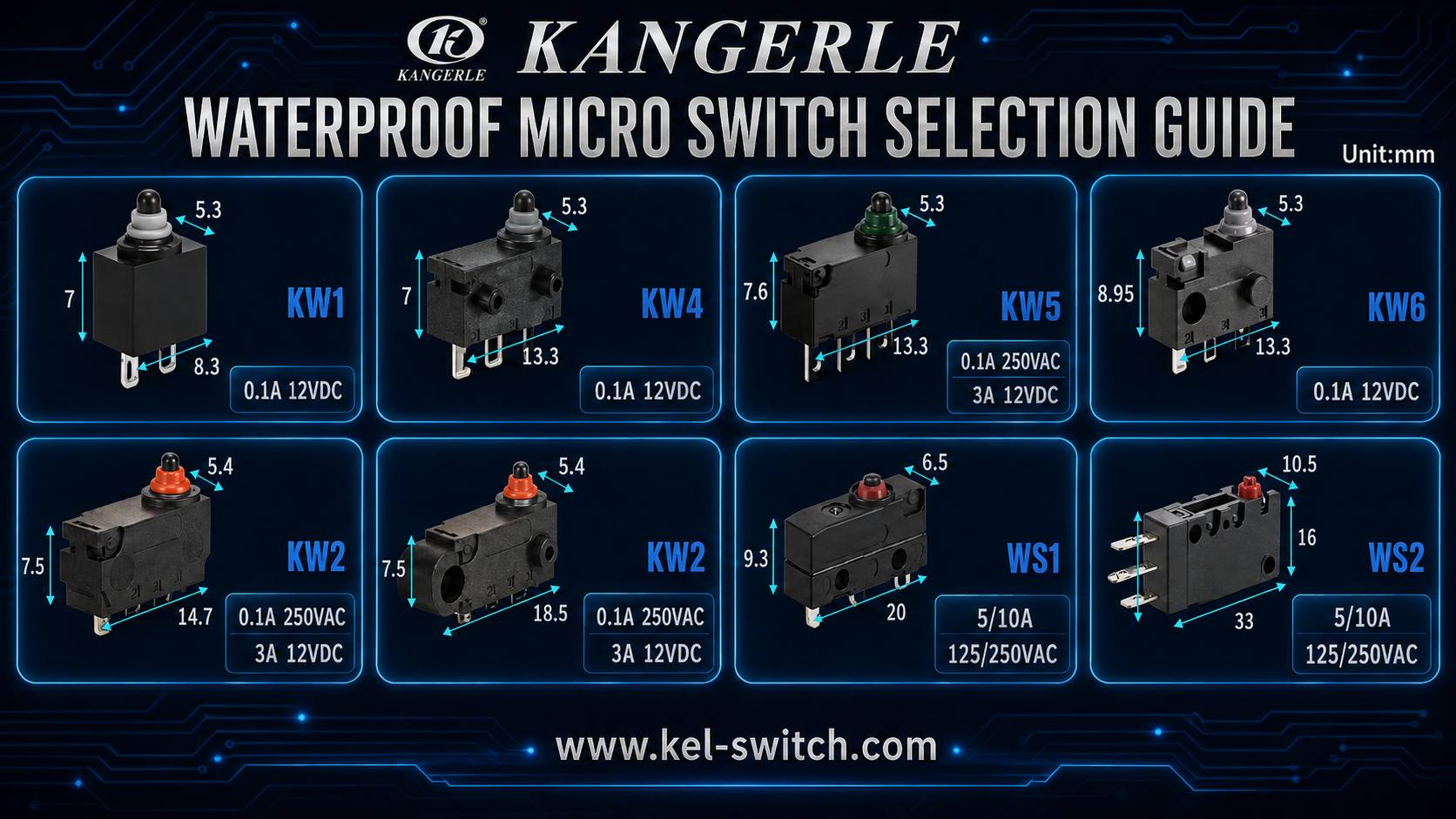
The series parameters in the selection catalog are summarized below. The dimensions are the main outline dimensions shown in the illustrations and are intended for rapid screening; the complete part number will still affect the contact configuration, lever, terminals, operating force, operating position, and wire-exit method.
| مسلسل | Rating | Main dimensions (mm) | Actuator/operating force | Life (operations) |
|---|---|---|---|---|
| KW1 | 0.1A/12VDC | 8.3×5.3×7.0 | Plunger; 120±30gf | Electrical 100,000 / Mechanical 300,000 |
| KW7 | 0.1A/12VDC | 8.3×5.3×7.85 | Lever; ≤300gf | Electrical 100,000 / Mechanical 300,000 |
| KW6 | 0.1A/12VDC | 13.3×5.3×8.95 | Plunger; ≤150gf | Electrical 100,000 / Mechanical 300,000 |
| KW4 | 0.1A/12VDC | 13.3×5.3×7.0 | Lever; ≤150gf | Electrical 100,000 / Mechanical 300,000 |
| KW5 | 3A/12VDC | 13.3×5.3×7.6 | Plunger; ≤150gf | Electrical 100,000 / Mechanical 300,000 |
| KW2 | 3A/12VDC | 14.7×5.4×7.5 | Plunger/lever/with screw holes; ≤150gf | Electrical 100,000 / Mechanical 500,000 |
| WS1 | 10A/250VAC | 19.9×6.5×9.3 (medium) | Plunger; ≤350gf | Electrical 10,000 / Mechanical 1,000,000 |
| WS2 | 10A/250VAC | 33×10.3×15.9 (large) | Plunger; ≤250gf | Electrical 10,000 / Mechanical 1,000,000 |
| KW5 flanged cover A/B/C | 3A/12VDC | Flange outline varies by version | Fixed mounting with leads; ≤150gf | Electrical 100,000 / Mechanical 500,000 |
Quick summary: KW1/KW7 are ultra-subminiature; KW2/KW4/KW5/KW6 are small; KW5 can be fitted with a flange; WS1 is a medium waterproof microswitch; and WS2 is a large waterproof microswitch. By current rating: KW1/KW7/KW4/KW6 are 0.1A/12VDC, KW2/KW5 are 3A/12VDC, and WS1/WS2 are 10A/250VAC.
ZHEJIANG KANGERLE ELECTRONICS CO. LTD: Automotive Switch Supplier
ZHEJIANG KANGERLE ELECTRONICS CO. LTD is located in Yueqing, Wenzhou, and was established in 1993. Its in-house products mainly include waterproof microswitches, standard microswitches, and detection switches, which are used in automotive equipment, household appliances, industrial control, security electronics, consumer electronics, and other fields.
Manufacturing Capabilities and Project Support
The company’s manufacturing processes cover mold design, mold manufacturing, precision stamping, injection molding, component machining, automated assembly, and automated testing. Its laboratory can perform high- and low-temperature testing, life testing, dimensional measurement, operating-force testing, contact-resistance testing, and material analysis.
The company operates in accordance with the ISO 9001:2015 and IATF 16949:2016 quality management systems. Depending on the specific model and project requirements, certification support such as UL, TÜV, CB, CE, CQC, and RoHS may be provided; the actual certifications of the selected model shall prevail.
Project support can cover housing dimensions, mounting holes, terminal direction, actuator structure, operating force, travel, wire harnesses, and environmental requirements. The development process can progress from technical selection and sample confirmation to functional testing, small-batch validation, and controlled volume supply.
Conclusion: Electrical First, Then Size, Followed by Complete-Assembly Validation
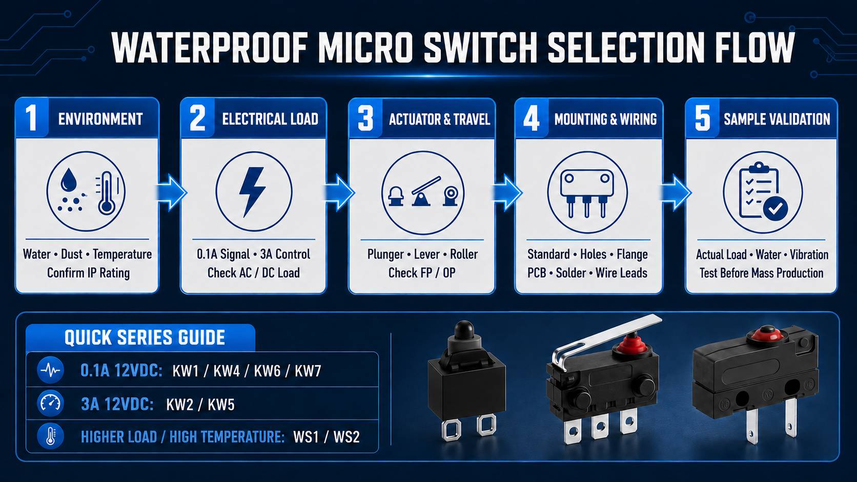
Selecting a waterproof microswitch can be straightforward: first use the operating voltage, current, and load type to eliminate series with mismatched ratings; then use the complete envelope of the switch body, actuator, terminals, or wire harness to eliminate series that will not fit; finally verify the plunger/lever, OP, operating force, IP67, temperature, life, and wiring.
A higher rated current is not necessarily more suitable. A larger switch may occupy more space and require greater actuation force, while a smaller signal switch cannot carry a load beyond its rated conditions. Comparing electrical parameters and mechanical dimensions in the same selection table is the key to reducing rework.
To complete selection more quickly, provide the following information together when requesting a quotation or samples:
- Application structure drawing or installation diagram
- Available mounting space and maximum envelope dimensions
- Mechanism movement direction and operating travel
- Operating voltage, steady-state current, peak/inrush current, and load type
- Contact configuration
- Temperature range and environmental requirements
- Target mechanical life and electrical life
- Wire-exit direction, wire length, and connector requirements
- Estimated annual usage
Final-selection recommendation: Complete the initial screening using the selection catalog, obtain the data sheet and 2D drawing for the complete part number, and finally confirm the selection through samples, the actual load, temperature cycling, vibration, and complete-assembly waterproof testing.
الأسئلة الشائعة (FAQ)
Which Automotive Waterproof Microswitch Should Be Selected for an EV Charging Connector?
The selection catalog recommends comparing KW1, KW2, KW5, and the KW5 flanged cover. For a 0.1A/12VDC low-current signal and extremely limited space, first consider KW1. When 3A/12VDC is required, consider KW2 or KW5. When a fixed mounting surface and lead wires are required, consider the KW5 flanged cover. The actuation motion, OP, wire harness, and complete-assembly waterproofing must still be verified.
For an Electric Two-Wheeler Brake Switch, Should You Choose KW1, KW2, or KW7?
First check the rating: compare KW1 and KW7 for a low-current signal, and compare KW2 for 3A/12VDC. Then check the motion: direct pressing is suitable for the plunger-type KW1; when the lever moves along an arc or assembly tolerances are large, the KW7 lever is more suitable. If a 3A rating and screw-positioned mounting are required, further compare the KW2 version with screw holes.
Is an IP67 Microswitch Suitable for an Automotive Door Lock?
For door-lock and tailgate applications that may be exposed to dust, splashing water, and temporary immersion, IP67 is a practical starting point for selection. However, the complete assembly must still be validated, because some models can achieve IP67 only after wiring is completed. The connector, wire outlet, housing seams, and wire routing must all meet the actual environmental requirements.
How Should Plunger-Type and Lever-Type Microswitches Be Selected?
When the moving component approaches the switch from the front and the operating position is accurately controlled, a plunger type may be selected. When the mechanism moves along an arc, approaches from the side, or has relatively large dimensional tolerances, a lever type is more suitable. For a sliding cam or continuously moving surface, a roller lever can be selected to reduce friction with the actuator.
When Dimensions Are Similar, What Should Be Compared First?
First compare the rating and operating force, and then compare OP, actuator structure, and terminal direction. For example, the body widths of KW4 and KW5 are both approximately 5.3 mm, but KW4 is rated 0.1A/12VDC and KW5 is rated 3A/12VDC. They cannot substitute for each other merely because their dimensions are similar.
What Is the Difference Between Mechanical Life and Electrical Life?
Mechanical life is the number of operations that the switch mechanism can withstand under specified test conditions. Electrical life also includes contact wear generated while switching a load. Electrical life is usually lower than mechanical life, especially with high current, inrush current, or inductive loads. Actual service life should be evaluated with reference to the electrical life under the corresponding load conditions.
Can the 10A/250VAC WS1/WS2 Directly Control a 12VDC Motor?
No. The 10A/250VAC rating of WS1 and WS2 is an AC rating and cannot be directly converted into switching capability for a 12VDC motor. Automotive motors also involve starting current, stall current, inductive back voltage, and target life. Before final selection, review the complete data sheet and test with the actual motor, protection circuit, and target number of operations.